


19
1 - M
ਮਲ਼ਮਨਹਤਣ
U
ਭਨਲ਼
WARNING
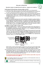
Failure to select and follow the mast tie installation schedule appropriate for the confi guration
could adversely aff ect worker safety, leading to serious injury or death and equipment damage.
It is
mandatory
to refer to the
Mast Tie Schedule
tables on p. 87 of the
Mast and Mast Ties
section before the installation of any F2 Series confi guration. It is also
mandatory
to refer
to the
Load Capacities
section on p. 94 for more information about the loads allowed in a
confi guration. Review and follow the instructions included in this manual for the installation and
use of each accessory and equipment to be installed.
Safety Guidelines
Setup and Confi gurations
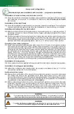
WARNING
It is important to note that freestanding confi gurations are not allowed for F2 Series
motorized units unless an optional adapter base for freestanding installation is used.
1-
Installation must be carried out by qualifi ed erectors/dismantlers under the supervision
of a competent person, in accordance with all applicable local regulations.
2-
In reference to the plan/layout drawing, make sure that all the components required are
available. Establish the position of the motorized unit, determine if there are obstacles
and what are the cribbing and mast tie requirements.
3-
Before installing the motorized unit, determine where the cribbing under the base will
rest. The bearing surface under the cribbing must be level, clear of debris and have
the proper bearing capacity (see the
Minimum Bearing Surface Capacities
table, on
p. 16). Should the actual bearing capacity be inferior to the values in the table, seek
instructions and recommendations from the site engineer. It is important to note that
the jacks on the lateral base extensions are designed to level the motorized unit
and must not be used to support the load nor the motorized unit
.
4-
Distance between the front edge of the main frame of the motorized unit and the fi nished
wall must be the number of planks multiplied by the width of one plank, while allowing
6" to 8" (15 to 20 cm) of play. Add an additional 2" (5 cm) if using a toe board. Refer
to applicable local regulations to determine play or the maximum allowable distance
between the motorized unit, including its accessories, and the face of the work.
5-
Make sure that all loads have been removed from the platform and that all workers
have stepped down before lifting and transporting the motorized unit.
6-
Unload the motorized unit with a rough terrain forklift or a crane. It is important to
consider the weight of the F2 Series unit to be lifted. Refer to p. 12 of the
Motorized
Unit
section for the weights of all F2 motorized unit models, both gas-powered and
electrical. For more information about lifting and moving a motorized unit, refer to
p. 131 of the
Transport, Storage and Maintenance
section.
7-
Proceed to the following instruction steps for the installation of the setup, as the
confi guration requires.


