background image

HMG 3010


Page 61


Edition 2013-03-26 - V04 R01 


Part No.: 669855 

Tracker: 

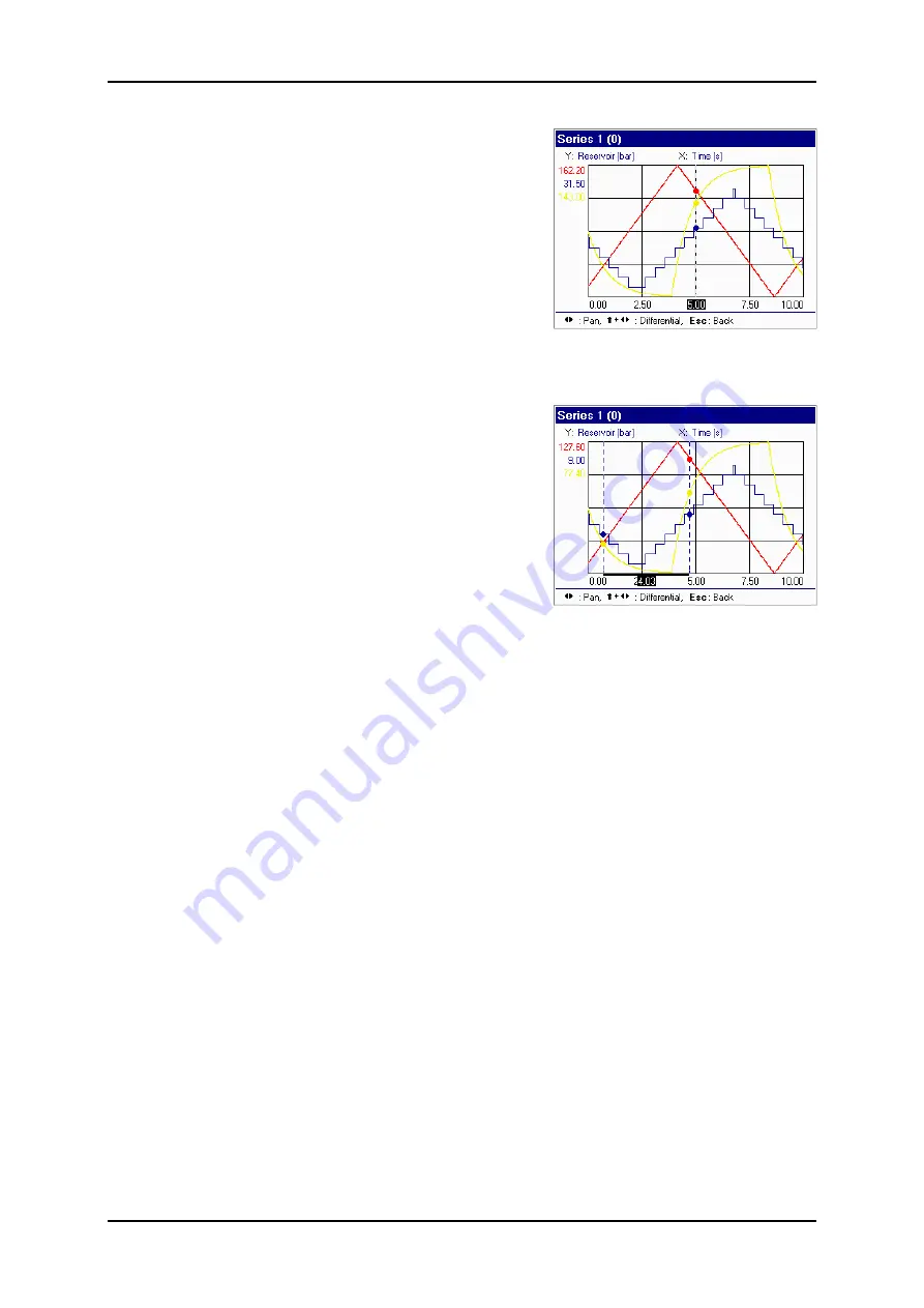
Using  the 

Tracker

  is  similar  to  using  the 

ruler. The difference is that each 

value

 ac-

tually  measured  is 

rendered  by  a point

. A 

ruler only appears for the purpose of "track-
ing"  the  curve  in  time.  The  tracker  "jumps" 
from  one  measurement  point  to  the  next, 
with the respective measured value of each 
measurement  channel  shown  along  the 
y-axis to this point x in time (x-axis). 
 
Here, too, the differential between a selected 
starting  and  end  point  of  a  particular  curve 
section  (e.g.  of  a  pressure  pulse)  can  be 
rendered and measured. 
 
To exit the 

Tracker

, press 

Esc


Undo: 
Undo

  enables  you  to  undo  any  changes 

(e.g. 

Automatic

Navigate

Zoom

) you have 

made, step by step. 
 

Performing measurements using the tracker 
 

Содержание HMG 3010

Страница 1: ...Edition 2013 03 26 V04 R01 Part No 669855 Portable Data Recorder HMG 3010 User Manual Translation of original instructions ...

Страница 2: ...HMG 3010 Page 2 Edition 2013 03 26 V04 R01 Part No 669855 ...

Страница 3: ... Operating Instructions 18 6 1 Settings Menu 18 6 1 1 Change settings of measurement channels 18 6 1 2 Changing Display Settings 29 6 1 3 Zeroing Measurement Channels 31 6 1 4 Changing the Initial Setup 33 6 1 5 Administer settings save load 36 6 2 Recording Menu 38 6 2 1 Starting a Recording 38 6 2 2 Viewing Recordings 56 6 2 3 Deleting Recording 67 6 3 Extras Menu 68 6 4 SMART sensors 70 6 4 1 C...

Страница 4: ... measurement data on a long term basis In addition depending on the sensor type preset parameters can be changed and stored in the internal memory as a sensor configu ration Older model HYDAC sensors or commonly available sensors made by other manufacturers can also be used However these sensors do not have any automatic sensor detection consequently the initial set up has to be entered manually T...

Страница 5: ...addition to enabling simple measurement curves to be recorded the HMG 3010 also has other functions enabling event driven measurements to be taken and event logs to be rec orded Various trigger options are available for triggering events Apart from measurement curves the HMG 3010 can store user specific settings user pro files The main advantage of this is to enable identical measurements of vario...

Страница 6: ...d directly from your computer The HYDAC software CMWIN is also supplied as standard with the unit This software enables you to communicate directly from your computer with SMART sensors connect ed to the HMG 3010 1 2 CAN functions of the HMG 3010 Option of connection to CAN bus using CAN adapter ZBE 3010 accessory Read out and evaluation of up to 32 measured values from up to 32 CAN messages Confi...

Страница 7: ... Technical Safety The individual components of the HMG 3010 portable data recorder and the assembled unit are subject to strict quality assurance inspection and testing Each HMG 3010 undergoes a final test This ensures that when supplied the unit is free of defects and complies with the published specifications The series HMG 3010 portable data recorders are maintenance free and work perfectly whe...

Страница 8: ...is in perfect condition working order The instructions for use must be strictly adhered to Functions which involve adjust ing the zero point in particular can lead to hazardous situations For more infor mation please refer to Point 6 1 3 Zeroing of Measurement Channels If sensors and interfaces are used simultaneously online measurement please ensure equipotential see chapter 6 1 4 PC Connection T...

Страница 9: ... x y z and A B C X Y Z ins insert del delete To insert special characters shift 1 if necessary several times for To insert spaces shift ins simultaneously To delete characters shift del simultaneously Line break shift OK simultaneously Tip To accept characters release the Shift key or press the right arrow of the 5 way navigation key To jump directly to the function line simultaneously press the S...

Страница 10: ...ging in Y adapters ZBE 38 For connection to CAN bus For connection to CAN bus use connection adapter ZBE 3010 see Point 6 5 Caution When connecting to CAN bus a Y adapter cannot be used on this input socket 1 input socket for 2 digital signals e g for frequency or speed measurements channel I J Female jack for power supply 1 USB connector for PC communication 1 serial interface for PC communicatio...

Страница 11: ...s are shown in the Current Measured Values menu see title bar at top of display To skip through the start up screen more quickly and proceed di rectly to the measured values menu press Esc or OK The following is listed in the measured values screen see screenshot Input channel Des ignation Value Unit of measurement The menu bar at the bottom of the screen function bar displays the main menu and ne...

Страница 12: ...is period Reset ting causes the Min Max values to be set to the actual measured value at the time This will reset all sensors The time period always begins when the Min Max values are reset The values are reset in the following situations Switching the unit on Selecting and activating Reset function in the menu bar only if Min Max is active Connecting or removing an HSI sensor Altering the sensor ...

Страница 13: ...he HMG you can simply restore the unit to its as supplied condition see Manage Settings Restore Factory Settings Preparation for Performing a Measurement First charge the batteries or connect the power supply as described in Power Supply Two HYDAC HDA 4748 H 0400 000 pressure transmitters with automatic sensor detec tion are used in the following example Example of a Simple Measurement Us ing Two ...

Страница 14: ...n Max display When the Min Max values are shown Reset appears in the function bar enabling you to reset the Min Max values as required Select Reset using the arrow keys blue highlight and then press the OK key to reset the Min Max values The measured values can also be displayed in a 7 segment pane To do this go to Set tings in the function bar and then press OK In the Settings menu navigate to Ch...

Страница 15: ...Recording menu that follows select Start recording and confirm with OK In the menu that follows Start Recording you are shown the default settings for re cording a measurement curve In our exam ple we want to generate a Simple meas urement curve with two sensors at chan nels A and B with a sampling rate of 1 ms and a Recording time of 30 s Then meas urement is to be finished Simple measurement cur...

Страница 16: ...ond option Your display now shows the settings you made for recording measured values see screenshot To double check your settings refer to the recorded data selected by you above the function bar Now you can start recording by pressing Start in the function bar OK A progress bar shows you the status of your measure ment The function bar offers you the option of having the measurement curve plotte...

Страница 17: ...ve plotted for our example When recording is finished you have the option of saving or discarding the measure ment To save the recording select Save and confirm with OK The HMG automatical ly assigns a name and a consecutive num ber which can also be renamed by you In our example accept the name suggested by the HMG and save with OK You can view any stored recording again or delete it as you like ...

Страница 18: ...nnels Select Change settings of measurement channels to obtain a listing of all the chan nels available in the HMG see screenshot There is a checkbox next to each of the channels enabling you to switch the input on or off OK key Activated channels are marked by an X To the right of the checkbox is the measurement range set ting the unit of measurement and as applicable a designation for the sensor...

Страница 19: ...tection HSI option is used for HYDAC sensors which have auto matic sensor detection The Manual setting is used for adapting sensors with standard analogue signals e g 4 20 mA to the HMG However there are applications for which it is useful to enter settings manually also in the case of HSI sensors with sensor recogni tion For example by entering settings man ually for a pressure measurement you ca...

Страница 20: ... e g kPa for kilopascal To enter additional characters move the triangle insertion point to the desired posi tion and enter the characters Confirm your entry with OK so that your unit of meas urement is stored Decimal format Here you can specify how many decimal places are to be used when recording and displaying the measured val ues In addition to the settings described above Channel B has two fu...

Страница 21: ...l A and channel B The differential meas urement range is produced automatically being 10 of the measurement range of the pressure transmitters connected The accuracy of the HSI pressure transmitters is 0 5 FS This means that one 100 bar pressure transmitter might measure 50 bar pressure as being 49 5 bar and another might measure it as 50 5 bar These pressure transmitter errors can be compensated ...

Страница 22: ...ack or the Esc key The HMG 3010 automatically selects the appropriate curve If you quit the menu and the HMG 3010 detects that no curve exists for this combination you will get the message shown on the right You can now with less accuracy measure the differ ential or you call the menu item again to rec ord a new curve under Organise curves Once Organise curves is selected a screen appears which al...

Страница 23: ...ample above to measure the filter contamination level both pressure transmitters might be fitted to the inlet side of the filter e g using T fittings and then with the machine running the curve could be recorded When these pre conditions are in place select Record characteristic curve This brings up a display showing 0 to 100 of the whole measurement range If you increase the pressure you will see...

Страница 24: ... at 350 l min Enter these values under the flow rate and pres sure Here again the menu Organise curves appears for a function description and handling see Pressure differential dP above Curve recording can be carried out exactly as de scribed above If you are using a HYDAC EVS 1000 flow rate measurement orifice you can also use this to record curves On the EVS 1000 there are 2 pressure ports befor...

Страница 25: ...o 30000 is possible in the graphical dis play If for example you record a speed of up to 1450 rpm an awkward Y axis scale will result in the graph If you enter 1500 as the Upper measurement range for this speed measurement for example the Y axis in the graph will be scaled from 0 to 1500 rpm In this case the reason for inputting the upper measurement range is just a means of limiting the scale of ...

Страница 26: ...s per minute for the graphical dis play the Y axis is scaled from 0 to 3000 3 A flow rate measurement transmitter in a measurement range up to 450 l min with a frequency output supplies 8 pulses per litre Enter 8 as the Factor and 500 as the Up per measurem range The display is then in l min for the graphical display the Y axis is scaled from 0 to 500 Examples of count pulses 1 The switching outpu...

Страница 27: ...nput channels or to calculate a power When setting to Differential the HMG 3010 calculates for channel K the difference be tween channel A channel B and for channel L the difference between channel C channel D To measure the differential sensors with the same measurement range unit of meas urement and number of decimal places must be used on the input channels These pa rameters are then automatica...

Страница 28: ...is brings you back again to the display shown on the right In the example a power is shown at channel K and the difference at channel L If you have made an invalid setting or you have connected 2 sensors with different measurement ranges for the differential for example the relevant calculated channel is deactivated In the example a pressure transmitter with measurement range of 0 100 bar has been...

Страница 29: ... ena bling you to choose the rendering speed Fast Medium Slow Delayed Make your selection followed by OK For Measured value rendering you can choose between the measured value table and various 7 segment display formats 1 display panel 2 display panels Set au tomatically When selecting Set automatically the HMG automatically searches for the optimal rendering When two sensors are connected and act...

Страница 30: ... the Display settings menu there is a Yes No option next to Show progress bar When Yes is selected the progress bar is also shown in the measured value display The appearance of the display may vary according to what settings have been made for rendering the measured val ues The overall width of the particular progress bar corresponds to 0 100 of the meas urement range The progress bar shows the p...

Страница 31: ...ment channels and then confirm with OK The screen on the right appears You are now prompted to select a measurement channel Select the channel checkbox which you would like to zero using the arrow keys and then confirm with OK Then select Set followed by OK you have zeroed the channel You can delete the changed zero point by pressing Delete All measurement channels which have been re zeroed are in...

Страница 32: ... value of the zero offset is shown on the right Any zero offset is also shown in the meas urement channel list by way of a small arrow in front of the measurement range To find it go to the Settings menu then Change Set tings of Measurement Channel OK There is one exception where the zero offset is automatically deleted This happens when a sensor is connected to the channel and this sensor has a d...

Страница 33: ...icable to the date and time Make your selection followed by OK Then enter the actual date and or time of day using the number pad Save by pressing OK Automatic Measurement Units This subitem refers only to HSI sensors with automatic sensor detection When the sensors are connected the unit of measure ment of the sensor is read out and automati cally adopted If for example you want all pressure tran...

Страница 34: ...ment Channel Settings Select the unit of measurement to be changed followed by OK Select the new unit of measurement desired from the drop down list by pressing OK In the list of measurement channels the measurement range for this channel is now shown in 0 1450 psi instead of in 0 100 bar for example In the current measured values display the measured values show psi readings listed after the chan...

Страница 35: ...aud rate Ground potential of the sensor ports and interfaces USB serial are connected gal vanically If sensors and interfaces are used simultaneously online measurement please ensure equipotential bonding to avoid transient currents between the electricity grids with different ground potential via HMG as the device could be destroyed Only for connection to CAN bus CAN Baud Rate kBit Under the menu...

Страница 36: ...er Settings menu with its four submenus see screenshot When you confirm Save current settings with OK you see the name of the setting saved last or No Name if nothing was saved Confirm with OK and you are shown a list of all the saved settings and or the op tion of entering a new name Select New Name and enter a name using the combina tion keypad Press OK x 2 to save the new name and to return to ...

Страница 37: ...enabling you to accordingly Load or Delete the setting You can restore your HMG to the original factory settings by selecting Restore factory settings see right Confirm Restore factory settings with OK and the menu following offers you two op tions Select the required function check box followed by OK and execute the option via the Execute command in the function bar Caution Initilize unit will de...

Страница 38: ...set for making a recording When selecting the first item Re cording a drop down list appears in which you can choose between Simple measure ment curve Measurement curve with trigger or Event log Select appropriate recording option followed by OK Select Simple measurement curve to make additional parameter settings Measurement channels The active measurement channels are shown here Confirm with OK ...

Страница 39: ...the 500 000 maximum you are shown a message in lieu of the recorded data describing the invalid setting made by you The sampling rate selected depends primari ly on the measurement task at hand A sam pling rate of 1 s is probably sufficient for monitoring the temperature in a hydraulic tank as temperature changes generally pro gress slowly If however you want to track extremely rapid system induce...

Страница 40: ... is shown at the bottom of the display pertaining to the recorded data showing you the result of your setting Recording option The options available here are End when time has elapsed and Record continuous ly until terminated End when time has elapsed means that recording is discontinued when the time en tered in Recording time has elapsed Record continuously until terminated means that the oldest...

Страница 41: ... conditions When the stop condition occurs again it is saved under a consecutive number This continues until the automatic recording is ended with Autostop and subsequent stop condition or the memory is full The automatic operation reverts automatical ly to deactivated each time a recording is stopped and must be activated again as required Zoomed area With the zoomed area an additional dis play a...

Страница 42: ...rting a recording You see a list showing the start time date time the time elapsed and the number of data records recorded A progress bar shows you the status of your recording The function bar offers you the option of having the measurement curve plotted graph or the current measured values dis played Graphic rendering provides a faster visual impression of the changes in the meas ured values To ...

Страница 43: ...cally as signs a name and a consecutive number both of which can be subsequently changed by you Select the appropriate item OK and make your entries using the combina tion keypad The Comment item enables you to enter text e g a description indicating the opera tional status of the unit or facility while the recording was being made To save the recording select Save and con firm with OK The HMG sav...

Страница 44: ...mpling rate and Recording time Automatic operation and Zoomed area The additional settings are Trigger settings and Pre Post trigger Select Trigger setting OK In the menu which follows you can specify up to 4 differ ent trigger events event 1 to 4 To activate an event select the relevant box by pressing OK so that a checkmark appears The event used last is shown next to the checkbox What appears i...

Страница 45: ...gs menu see screenshot you specify the trigger input under Input Only the two digital inputs I and J are available here Next you set the Slope to rising or falling and confirm with OK Event Specific value Use the trigger event Specific value to lo cate pressure peaks or pressure troughs in a machine Pressure peaks always occur in a rising direction measured value increases whereas pressure troughs...

Страница 46: ...on Timed is useful for measurements which are to be repeated at specific intervals In the Settings menu you can specify the num ber of Repetitions max 30 000 the Inter val and the Starting time In the Start item you can specify whether this event is to be activated immediately Start immediately or not until after a certain Start date and Start time In the Event Timed example shown on the right a m...

Страница 47: ...red value in channel A drops to 5 00 bar with the measured value in channel B leaving the window of 4 00 to 6 00 bar at the same time OR a voltage signal falling signal edge is detected at trigger input J OR a key or button is actuated Other event linking options are shown in the drop down list It should be borne in mind that events are always listed in descending order otherwise you have to re so...

Страница 48: ...after the event A Pre post trigger setting of 50 50 means that for a recording time of 30 s the oldest 15 s are discarded 15 s remain be fore the occurrence of the event and record ing is done for another 15 s after the trigger event occurs With Automatic mode you define whether you wish to make just one recording De activated or whether after recording one measurement curve another curve is to be...

Страница 49: ...hannel A increases to 180 bar Event 2 channel B increases to 230 bar Event 3 channel C increases to 280 bar Each of these pressures is 50 bar higher than is normally allowed Pre post trigger 80 20 You select this option because you are interested in knowing what happened in the other pressure circuits before the trig ger was actuated and you want to record the pressure curve somewhat longer after ...

Страница 50: ...ting Stop This cancels the current measurement and activates a new measurement automatically To end automatic measurement select Au tostop followed by OK After ending automatic measurement the result obtained is a series of measurements which can be viewed as a list via View re cording To do this select View recording in the Recording menu you are now shown all of the measurement curves just recor...

Страница 51: ... trigger in automatic measurement you can also choose whether you would like to make just one recording or whether an event log is to be recorded again afterwards using the same settings Example of an Event Log In order to gauge the quality of a stamping operation the stamping machine is to be monitored for two hours Proper stamping requires a die closing pressure of between 127 bar and 132 bar In...

Страница 52: ...rs For the above example this means that the stamping press is switched on the pressure reaches 131 bar and drops back to 0 bar When reaching 5 bar in the falling direction a measured value line is generated and the Min Max values are reset The last Max val ue is retained in the measured value line A die closing pressure of 129 bar is reached in the next cycle This value is also written to a new l...

Страница 53: ...ou are shown an overview of the event log and are prompted to Save your recording or Discard it function bar Before doing this the measurement can be shown again as a curve Graph OK or table Table OK Other tools are also available For more information please refer to the next section Viewing Recordings It provides a detailed description of the options available and how to use the tools and other f...

Страница 54: ...tic measurement Activated and start the meas urement with Start you are asked to allocate a Name and a Number to the measurement The measurement is then stored under this name with the next consecutive number In the function bar on the screen you also see the Autostop function The measurement currently running can be ended by selecting Stop This measurement will then be saved and a new measurement...

Страница 55: ...firm with OK Under Recording time define the time at which the measurement must stop automati cally if the Trigger Condition 2 Stop has not occurred by then With Automatic mode you define whether you wish to make just one measurement Deactivated or whether after recording one measurement curve another curve is to be recorded using the same settings Acti vated Zoomed area With the zoomed area an ad...

Страница 56: ...e from the selection list to the menu in the next level up The arrow key enables you to access the header row The list can be sorted accordingly by press ing OK To do this select Name Number or Recording started in the header row To sort in ascending or descending order click in the relevant column header with OK press ing OK more than once will reverse the sort ing order An arrow next to the colu...

Страница 57: ...is to another channel activated for display This opens a drop down box in which all channels are listed Select one followed by OK to specify y axis display The axis is displayed in the same colour as the associated measure ment value curve see below Press to go to the setting field for the x axis Here you can change the Scaling for the x axis in the same way As a general rule the x axis is the tim...

Страница 58: ...uate a measure ment curve quickly and accurately or to ren der parts of it It enables the size of the curve to be changed or the measurement curve to be shifted so that details can be rendered more accurately and analyzed more easily When selecting Navigate you are shown information in the function bar about the ac tivities possible here including graphical tips for using them Use the arrow keys o...

Страница 59: ... ture see previous page A frame or zoom window appears in the middle of the graph The position and size of the zoom can be changed using the 5 way navkey and the Shift key similar to Navigate Use the arrow keys and to shift the zoom window to any place in the graph To resize the zoom window in addition to shifting it using the arrow keys hold the Shift key down When the zoom is set and positioned ...

Страница 60: ...e a pressure pulse in time and amplitude for example use the Differential function Proceed as follows First shift the x and y ruler to the starting point of the pressure pulse using the arrow keys Then press the Shift key in addition to the arrow keys and hold it down As soon as you actuate one of the arrow keys a second x and y ruler appears which you can move to the end point of the pressure pul...

Страница 61: ...s from one measurement point to the next with the respective measured value of each measurement channel shown along the y axis to this point x in time x axis Here too the differential between a selected starting and end point of a particular curve section e g of a pressure pulse can be rendered and measured To exit the Tracker press Esc Undo Undo enables you to undo any changes e g Automatic Navig...

Страница 62: ...ording The channel rendered along the y axis in the measurement curve is addition ally labelled with Y For rendering as a graph you can activate or deactivate a channel by checking or un checking the box in front of it using the ar row keys OK checkmarked means that the channel will be shown This enables you to specify whether all measurement chan nels are to be shown or only one or two at a time ...

Страница 63: ...rming the Lower limit line with OK you can change the value Save your entry with OK You are now in the next line If required the upper limit can be reset in exactly the same way For Line style a drop down list appears of fering you a choice of Solid line Dotted line and Dash dotted line Make your se lection confirming with OK Colour use the arrow keys to select various colours from a list confirmi...

Страница 64: ...g lower and upper limit of y axis 0 50 bar Control line Time range of x axis 4 00 6 00 s Time Info The last item Info in the graph screen is used to view and modify comments entered by you comments are entered using the combination keypad You can also have the recording data for a measurement displayed To exit the Info menu use Back The exit the graph use Back or Esc ...

Страница 65: ...e data record is shown per row for each event Each individual data record con sists of the date time trigger event and the associated measured values of the individual channels including the Min and Max values The data record of the event recorded last is contained in the bottom line of the table When more than one channel is used the tables of measurements in general and event logs in particular ...

Страница 66: ...c place in the table via the date and time setting in the column next to the beginning of the ta ble Select with OK enter the desired time using the combination keypad and finish with OK Select Table to take you back to table display Info is used to view and modify comments previously entered make your entries using the combination keypad It also enables you to display the recorded data for a meas...

Страница 67: ... header row Press OK to sort the list according to Name Number or Recording started To do this select Name Number or Recording started in the header row using the arrow keys To sort in ascending or descending order click in the relevant column header with OK pressing OK more than once will reverse the sorting order An arrow next to the col umn header indicates whether sorting is in ascending or de...

Страница 68: ...opwatch Use Back or Esc to switch back to normal measurement mode The stopwatch continues to run in the back ground As soon as you have completed troubleshooting call up the Stopwatch menu again and stop the clock using the Stop command Use Reset to set the stopwatch back to zero About HMG 3010 The About HMG 3010 menu provides an overview of available power supply how much memory is still free whe...

Страница 69: ... activate in the HMG 3010 CAUTION All data stored in the HMG 3010 measurements settings is deleted when the update is imported Back up this data to a PC using HMGWIN 3000 before starting the update Con nect the power supply to the HMG 3010 to ensure a secure voltage supply during the up date To activate the update select Update Instrument Software and then Start OK Once the update has been carried...

Страница 70: ...B 1300 The display settings and measured value renderings can be changed as described in section 6 1 2 above Since every SMART sensor goes through an initialization phase until the actual measured values are displayed we rec ommend resetting the Min and Max values after this phase has completed 6 4 1 Connecting SMART Sensors To connect SMART sensors with the HMG 3010 select the SMART Sensors optio...

Страница 71: ...ected SMART sen sor Part number Serial number Information about the various meas urement channels with regard to their type and measurement range 6 4 2 2 Sensor Values The actual measured values along with the associated units of measurement of the connected SMART sensor are shown here If the SMART sensor records Min Max values internally they are also shown if not a dotted line is shown 6 4 2 3 S...

Страница 72: ...n the SMART sensor connected For detailed information on the possible settings please refer to the particular sen sor documentation 6 4 2 5 Administer Sensor Configura tion Here you have the possibility of reading the current configuration of the SMART sensor or transferring saved settings into the SMART sensor You can also have a saved configuration displayed or deleted Read configuration from se...

Страница 73: ...you to display a configuration which is stored in the HMG 3010 You are then shown detailed information on the sensor configuration Delete stored sensor configuration This menu enables you to delete a sensor configuration Select the configuration concerned and select Delete on the function bar 6 4 2 6 Set sensor bus address This menu enables you to assign a bus address to a sensor To do this select...

Страница 74: ...the HMG 3010 using the 5 pole M12x1 connector cable If connected to a different input jack an error message will be displayed The CAN adapter ZBE 3010 must only be connected directly i e not using a Y adapter to jack D H on the HMG 3010 The HMG 3010 may only be connected to a CAN bus system via the CAN Adapter ZBE 3010 either via the M12x1 male connector or via the SUB D male connector both con ne...

Страница 75: ...D Female 18 V UB 6 5 2 Main menu CAN bus Navigate via Settings Change settings of measurement channels Channel D CAN bus to reach the main menu for CAN functionality and to be able to adapt this to your requirements If Channel D CAN bus is selected the dis play jumps to the following window 6 5 2 1 Sub channel 01 Sub channel 32 In this window you can activate and then configure up to 32 CAN messag...

Страница 76: ...ensor e g bar psi C etc Under Decimal format specify whether the measured value is to be displayed with a decimal place in the HMG CAN Data In the Frame Format line indicate whether the CAN message is in either Standard 11 bit or Extended 29 bit format In the Message Id line enter the hexadecimal coded message Id CAN Identifier of the relevant CAN message In the Data offset line indicate from whic...

Страница 77: ...which the databytes should follow one another in the message In the Lower data value and Upper data value enter the data values which the sensor delivers at the upper and lower measuring range final value The specified data range is then scaled in the measuring range Back takes you back to the previous screen Configure other CAN messages in the same way as described previously If CAN messages is s...

Страница 78: ...l for flow rate measurement orifice shown at channel B Channel I and J Frequency channels speed rpm measurement counting function Frequency range 1 30 000 Hz 0 1 FS max Switching threshold switch back threshold 2V 1V Max input voltage 50 V display delay max 2 s Overview of signals measurement inputs Measurement range accuracy Chann A Chann B Chann C Chann D Chann E Chann F Chann G Chann H HIS 0 1 ...

Страница 79: ...wing applies 0 1 ms max 2 analogue input channels 0 2 ms max 4 analogue input channels 0 5 ms all 10 input channels 1 0 ms for SMART sensors Measured value memory Single recording up to 500 000 measured values Archive memory 128 MB for min 100 individual recordings PC link interfaces USB port Serial interface RS 232 For communication and evaluation using the HYDAC HMGWIN 3000 or CMWIN software and...

Страница 80: ...r HDA 4748 H 0400 000 Part no 909428 Part descr HDA 4748 H 0600 000 Temperature Transmitter with HSI interface Part no 909298 Part descr ETS 4548 H 000 25 to 100 C Flow Rate Transmitter with HSI interface Part no 909293 Part descr EVS 3100 H 1 006 060 l min Part no 909403 Part descr EVS 3100 H 2 040 600 l min Part no 909404 Part descr EVS 3100 H 3 015 300 l min Part no 909405 Part descr EVS 3100 H...

Страница 81: ... 1000 Part no 909737 Part descr ZBE 36 connection adapter for AS 1000 Part no 910000 Part descr ZBE 41 Y adapter yellow for CS 1000 Part no 6040851 Part descr ZBE 30 02 sensor cable M12x1 5 pole 2m Part no 6040852 Part descr ZBE 30 05 sensor cable M12x1 5 pole 5m Part no 909752 Part descr UVM 3000 Adapter for non HYDAC sensors Part no 903083 Part descr Hydraulic adapter kit for the HMG Contents 2 ...

Страница 82: ...ure transmitters Flow rate transmitters Charger Connection cable HMG PC USB Pressure transducer Pin 1 12 V 50 mA 2 Channel E F G 3 Channel A B C 4 GND 5 HSI Pin 1 12 V 50 mA 2 Channel J 3 Channel I 4 GND 5 Analog input 10 V UVM 3000 A E B F C G D H Pin 1 12 V 50 mA 2 Channel H CAN_H 3 Channel D CAN_L 4 GND 5 HSI ...

Страница 83: ...855 9 1 Pin assignment Note on H Channel H can be used for sensors with an analogue signal connection to jack D H or for voltage measurements of 10 V to 10 V connection to jack T The input signal is selected when setting the measurement range for channel H ...

Страница 84: ...tor cable Jack socket 3 5 mm RS 232 For connecting the HMG to the serial port RS 232 of PC Connecting diagram pin assignment Ground potential of the sensor ports and interfaces USB serial are connected galvanically If sensors and interfaces are used simultaneously online measurement please ensure equipotential bonding to avoid transient currents between the electricity grids with different ground ...

Страница 85: ...e HYDAC SERVICE GMBH Hauptstr 27 D 66128 Saarbrücken Germany Phone 49 0 6897 509 1936 Fax 49 0 6897 509 1933 NOTE The information and particulars provided in this manual apply to the operating conditions and applications described herein In the event of deviating applications and or operating conditions please contact the respective HYDAC department concerned If you have any questions suggestions ...

Отзывы: