3.8
PARAMETER
DEFINITION
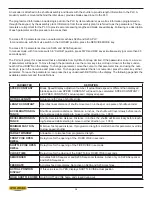
SPEED CONSTANT
Blade Speed Display adjustment number. If actual blade speed is different than displayed
blade speed, a new SPEED CONSTANT will need to be calculated. SPEED CONSTANT =
old SPEED CONSTANT x actual speed / displayed speed.
ACTUAL LENGTH
Actual Length Value of shuttle stroke.
LENGTH CONSTANT
6SHFL¿HVOLQHDUGLVWDQFHRIVKXWWOHPRYHPHQWLQLQFKHVSHURQHSXOVHRIVKXWWOHHQFRGHU
ACCELERATION DIS-
TANCE
Shuttle acceleration distance. Distance, in inches, the shuttle will travel slowly before reach-
ing fast speed while starting to move in either direction (i.e. 1.000).
DECELERATION DIS-
TANCE
Shuttle Deceleration distance. Distance, in inches, the shuttle will travel slowly before reach-
ing fast speed while starting to move in either direction (i.e. 1.000).
MINIMUM FAST DIS-
TANCE
Minimum fast speed distance. If programmed length is smaller than this parameter, override
to slow speed (shuttle)
TARGET WINDOW
All/- tolerance from programmed length.
FRONT VISE OPEN
DWELL
Delay time for the opening of the FIXED VISE in seconds.
SHUTTLE VISE OPEN
DWELL
Delay time for the opening of the FIXED VISE in seconds.
CLOSE TIME
Delay time for the closing of the SHUTTLE or FIXED VISE in seconds.
SEQUENCER
Activates S22A Sequencer and S23A Sequencer features. Active only on S22A Sequencer
and S23A Sequencer.
FEED RATE
Activates feed rate display. Not active on S20A and S23A machines.
ACTUAL POSITION
DISPLAY
If this value is set to YES, displays SHUTTLE VISE actual position
HOLD SHUTTLE HOME
Hold SHUTTLE VISE home and closed during cut.
An encoder is attached to the shuttle assembly and travels with the shuttle to provide length information to the PLC. A
proximity switch is mounted behind the idler wheel, provides blade speed input to the PLC.
The programmed information includes logic put into the PLC by its manufacturer, as well as information programmed in,
through the keypad, by the assembly plant. Information from the assembly plant is referred to as the parameters. The pa-
rameters are important for the PLC to provide accurate sawing lengths and blade speed display. Following is a description
of each parameter and the procedure to access them.
To access PLC parameters screen on automatic machines S22A and S23A PLC:
In manual mode, with front vise switch in the CLOSED position, press the SERVICE MODE key.
To access PLC parameters screen on S22A and S23A Sequencer:
In manual mode, with front vise switch in “CLOSE” position, press FWD and REV keys simultaneously (not more than 0.5
seconds apart).
The PLC will prompt for a password that is obtainable from Hyd·Mech Group Limited. If the password is correct, a screen
of parameters will appear. To move through the parameters use the cursor keys to scroll up or down or the keys under-
neath UP and DOWN on the display. To change a parameter, move the cursor to that parameter line, and using the num-
ber keys, type in the new value and press enter. To change a parameter that is not numerical, press the enter key at that
parameter. To leave the parameter screen press the key underneath RETURN on the display. The following page lists the
DYDLODEOHSDUDPHWHUVDQGWKHLUGH¿QLWLRQV
Содержание S-20 A
Страница 2: ......
Страница 16: ...1 4 ...
Страница 54: ......
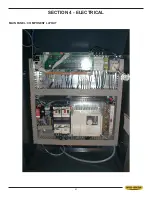
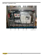
Страница 55: ...4 1 SECTION 4 ELECTRICAL MAIN PANEL COMPONENT LAYOUT ...
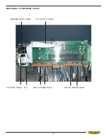
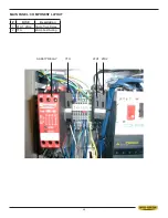
Страница 58: ...4 4 MAIN PANEL COMPONENT LAYOUT 1OL 2OL VFD 1M 2M POWER SUPPLY ...
Страница 63: ...5 3 FOR HYDRAULIC SCHEMATICS AND PLUMBING DIAGRAMS SEE PDF ON ATTACHED CD ...
Страница 64: ......
Страница 65: ...6 1 SECTION 6 MECHANICAL ASSEMBLIES For Mechanical Assembly Drawings see PDF on attached CD ...
Страница 66: ......
Страница 70: ......
Страница 72: ...8 2 ...
Страница 73: ...8 3 ...
Страница 74: ...8 4 ...
Страница 76: ...8 6 ...
Страница 77: ...8 7 ...
Страница 78: ...8 8 ...

