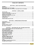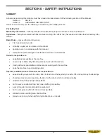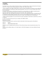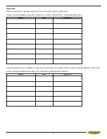
1.3
LEVELLING THE SAW
Use a machinist's level across the vise table to level the saw. Adjust the level with the leveling bolts supplied. Consider-
DWLRQVKRXOGEHJLYHQWRWKHÀRZRIWKHFRRODQWDVLWUHWXUQVWRWKHFRRODQWWURXJKDWWKHYLVHHQGRIWKHVDZ/HYHOLQJWR
give a small incline towards this area helps to ensure the coolant supply returns to the container.
HYDRAULIC OIL
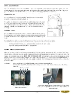
The S-20/23A option is supplied with ISO VG22 hydraulic oil. Substitutes
should be of the same viscosity hydraulic oil.
The cylinder contains oil in a reservoir that should be topped up to the level
RIWKH¿OOHUSOXJ$GGRLOWRWKHF\OLQGHURQO\ZLWKWKHKHDGLQWKHGRZQSRVL
-
tion. The head cylinder is a self air bleeding cylinder with a small port in the
top plate. If excess oil is displaced from this port, the cylinder is working
normally.
CUTTING FLUID
The S-20/23A uses a pump and reservoir to circulate the necessary cutting
ÀXLGWRWKHEODGHIRUPD[LPXPEODGHOLIH<RXUVDZEODGHVXSSOLHUZLOOEHDEOH
WRSURYLGHLQIRUPDWLRQWRWKHFXWWLQJÀXLGSURGXFWVWKDWDUHDYDLODEOHIRU\RXU
needs.
1RFXWWLQJÀXLGFRRODQWLVVXSSOLHGZLWKWKHPDFKLQH7KHUHDUHWZRW\SHVRIFRRODQWDYDLODEOH
- Oil based; dilute 1:10 ratio (one part concentrated coolant to 10 parts water)
- Synthetic; dilute as recommended by manufacturer.
POWER WIRING CONNECTIONS
When the machine has been anchored and leveled the power hook-up is the last installation step. In order to prevent po-
WHQWLDOGDPDJHWRWKHPDFKLQHRQO\TXDOL¿HGSHUVRQQHOVKRXOGPDNHWKHHOHFWULFDOFRQQHFWLRQV,IWKHK\GUDXOLFVGRHVQRW
register an immediate pressure rise,
SHUT THE HYDRAULIS OFF
and change the phase order. As supplied, your new
S-20/23 A is set to run on three phase voltage. The supply voltage of the macine is shown on the serial plate attached to
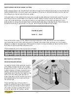
the front of the machine. Connection from the main supply is made to L1,L2, L3 and ground terminals in the electrical box
as shown below.
Check for:
Signs of damage to the electrical cables from shipping and/or installation.
Correct phase order. The blade should be running counter clockwise. If incorrect, two lines should be
reversed.
The power cable should be routed through the hole found
at the bottom right of the control box. A suitable strain relief
should be used.
Gnd L1 L2 L3
Main power connections found
inside the control box
Содержание S-20 A
Страница 2: ......
Страница 16: ...1 4 ...
Страница 54: ......
Страница 55: ...4 1 SECTION 4 ELECTRICAL MAIN PANEL COMPONENT LAYOUT ...
Страница 58: ...4 4 MAIN PANEL COMPONENT LAYOUT 1OL 2OL VFD 1M 2M POWER SUPPLY ...
Страница 63: ...5 3 FOR HYDRAULIC SCHEMATICS AND PLUMBING DIAGRAMS SEE PDF ON ATTACHED CD ...
Страница 64: ......
Страница 65: ...6 1 SECTION 6 MECHANICAL ASSEMBLIES For Mechanical Assembly Drawings see PDF on attached CD ...
Страница 66: ......
Страница 70: ......
Страница 72: ...8 2 ...
Страница 73: ...8 3 ...
Страница 74: ...8 4 ...
Страница 76: ...8 6 ...
Страница 77: ...8 7 ...
Страница 78: ...8 8 ...


