2.19
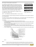
pitch changes for differing effective material widths.
It is impractical to change the blade to the proper pitch every time a
different width of material is cut and it is not necessary, but remember
WKDWWKHRSWLPXPEODGHZLOOFXWPRVWHI¿FLHQWO\7RR¿QHDEODGHPXVW
be fed slower on wide material because the small gullets between the
teeth will get packed with chips before they get across and out of the
cut. Too coarse a blade must be fed slower because it has fewer teeth
cutting and there is a limit to the depth of a cut taken by each tooth. Al-
lowance for the use of a non-optimum blade is made in STEP 5.
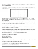
In our Example #1: Effective material width of 8” (200mm) and opti-
mum blade has 2/3 teeth per inch.
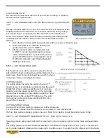
STEP 4 – DETERMINE OPTIMUM BLADE SPEED, V (ft./min/) (m/min.)
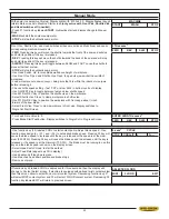
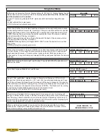
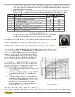
The relationship between optimum blade speed and effective material width for various materials is represent-
ed on the graph shown.
The graph shows that as effective material width gets wider or as material gets harder, lower blade speeds are
recommended. If material is narrow or soft, higher blade speeds should be selected.
In Example #1
x
8” (200mm) diameter #1045 Medium Carbon Steel solid bar is to be cut
x
2QWKHJUDSKDERYH¿QGWKH0HGLXP&DUERQ6WHHO&XUYHZKLFKUHSUHVHQWVWKHRSWLPXPEODGHVSHHGV
for 1045 Carbon Steel
x
2QWKHKRUL]RQWDOD[LVHIIHFWLYHPDWHULDOZLGWKD[LV¿QGQXPEHUZKLFKUHSUHVHQWVHIIHFWLYHPDWHULDO
width of an 8” (200mm) diameter solid
x
Find the point where a vertical line from 8” (200mm) intersects the Medium Carbon Steel Curve.
x
)URPWKLVLQWHUVHFWLRQSRLQWUXQKRUL]RQWDOO\OHIWWRWKHYHUWLFDOD[LVRSWLPXPEODGHVSHHGD[LVDQG¿QG
the point marked “200”
x
For an 8” (200mm) diameter, 1045 Carbon Steel solid bar, 200 ft./min. (60m/min.) is the optimum blade
speed
NOTE:
1. Higher than optimum blade speed will cause rapid blade dulling. Lower than optimum blade
VSHHGVUHGXFHFXWWLQJUDWHVSURSRUWLRQDWHO\DQGGRQRWUHVXOWLQVLJQL¿FDQWO\ORQJHUEODGHOLIHH[
-
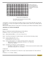
Optimum Blade Pitch ( T.P.I.
Optimum Blade Speed Curves
Содержание S-20 A
Страница 2: ......
Страница 16: ...1 4 ...
Страница 54: ......
Страница 55: ...4 1 SECTION 4 ELECTRICAL MAIN PANEL COMPONENT LAYOUT ...
Страница 58: ...4 4 MAIN PANEL COMPONENT LAYOUT 1OL 2OL VFD 1M 2M POWER SUPPLY ...
Страница 63: ...5 3 FOR HYDRAULIC SCHEMATICS AND PLUMBING DIAGRAMS SEE PDF ON ATTACHED CD ...
Страница 64: ......
Страница 65: ...6 1 SECTION 6 MECHANICAL ASSEMBLIES For Mechanical Assembly Drawings see PDF on attached CD ...
Страница 66: ......
Страница 70: ......
Страница 72: ...8 2 ...
Страница 73: ...8 3 ...
Страница 74: ...8 4 ...
Страница 76: ...8 6 ...
Страница 77: ...8 7 ...
Страница 78: ...8 8 ...

