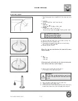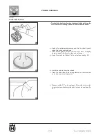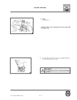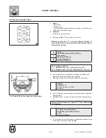
F1.32
Part. N. 8000 H4704 (07-2010)
60
61
62
ENGINE OVERHAUL
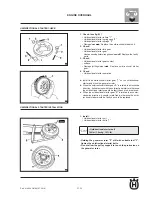
GENERAtOR REmOVAL
1. Remove:
• Generator rotor nut "1" (see fig. 60)
• Washer
WARNING!
protect crankshaft end by setting a suitably sized
•
socket wrench between flywheel puller kit cen
-
tring bolt and the crankshaft.
• Holding the generator rotor "2" with suitable tool "3", slacken
the generator rotor nut.
• Do not allow the pulley support to touch the protrusion on
the generator rotor.
2. Remove:
• Generator rotor "1"
(with flywheel puller "2")
• Woodruff key
• Make sure the flywheel puller is centred on the generator
rotor.
UNIdIRECtIONAL stARtER REmOVAL
1. Remove:
• Unidirectional starter bolts "1" (see fig. 62)
• Locking out the generator rotor "2" with suitable tool "3",
remove unidirectional starter bolts.
• Do not allow the pulley support to touch the protrusion on
the generator rotor.
Содержание SMS4
Страница 1: ...Workshop Manual TE 125 2011 SMS4 2011 Part N 8000H4704 07 2010 ...
Страница 6: ......
Страница 7: ...A 1 A Part N 8000 H4704 07 2010 GENERAL INFORMATION Section ...
Страница 14: ......
Страница 15: ...b 1 Part N 8000 H4704 07 2010 b IMPORTANT NOTICES Section ...
Страница 17: ...F 1 Part N 8000 H4704 07 2010 TECHNICAL DATA F Section ...
Страница 34: ...F 18 Part N 8000 H4707 07 2010 22 TECHNICAL DATA 1 Camshaft 2 Crankshaft 3 Input shaft 4 Output shaft ...
Страница 35: ......
Страница 36: ......
Страница 37: ...F1 1 Part N 8000 H4704 07 2010 F1 ENGINE OVERHAUL Section ...
Страница 109: ...F2 1 Part N 8000 H4704 07 2010 F2 MAINTENANCE Section ...
Страница 121: ...F3 1 Part N 8000 H4704 07 2010 F3 ENGINE COOLING Section ...
Страница 131: ...F4 1 Part N 8000 H4704 07 2010 F4 CARBURETTOR Section ...
Страница 132: ...F4 2 Part N 8000 H4704 07 2010 CARBURETTOR CARBURETTOR ...
Страница 136: ...F4 6 Part N 8000 H4704 07 2010 CARBURETTOR ...


