15
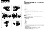
1. Remove crate top and sides.
2. Remove upper handle bar assembly and lay
aside.
3. Open bag containing loose hardware.
4. Using four (4) screws, flat washers and nuts
attach the upper handle bar assembly to lower
handle bar assembly.
NOTE: Handle fit is tight. When aligning holes use
a tapered type pilot to help align holes (i.e. punch
or phillips style screw driver).
5. Attach the position adjusting rod to bracket on the
upper handle bar assembly with the washers and
cotter pins placed above the rod bracket. Attach
the lower adjustment bar to the unit and secure
with cotter pin.
1
6. Assemble the compression spring, two (2) flat
washers and yoke to brake rod assembly.
7. Screw yoke onto the rod assembly until rod is
even or through threaded portion of yoke about ¼"
(6.35 mm).
8. Attach brake rod assembly to brake handle on the
upper handle bar assembly.
3
4
2
5
3
2
4
1
4
8064-027
1. Upper handle bar
2. Adjusting rod
3. Lower handle bar
4. Cotter pins
5. Washers
8060-039
1. Nut
2. Spring
3. Yoke
4. Washer
8060-040
1. Brake rod assembly
2. Brake handle
1
2
Содержание SG13
Страница 36: ...36 8064 026 For maintenance of the engine refer to the manufacturer s Owners Manual ...
Страница 45: ...45 SERVICE JOURNAL Action Date stamp signature ...
Страница 46: ...46 Action Date stamp signature ...
Страница 47: ......
Страница 48: ...Original instructions 2010 03 11 115 15 19 26 z SS 6I z SS 6I ...


