


8.11
Section 8
Disassembly
8
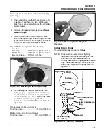
Figure 8-43. Separating Oil Pump Assembly from
Intake Side Cam Shaft.
Remove Connecting Rod and Piston
1. Rotate the crankshaft so the rod journal is in the
9 oclock position.
2. Remove the two hex. flange screws and the
connecting rod cap. See Figures 8-44.
NOTE: If a carbon ridge is present at the top of the
bore, use a ridge reamer to remove it before
attempting to remove the piston.
Figure 8-42. Intake Cam shaft and Oil Pump
Assembly.
5. If necessary, the oil pump can be separated from
the intake side cam shaft. Providing appropriate
support for the shaft, drive out the lower pin. The
oil pump assembly can then be removed from the
cam shaft. See Figure 8-43.
Figure 8-44. Removing Connecting Rod Cap.
3. Carefully push the connecting rod and the piston
away from the crankshaft and out of the cylinder
bore. See Figure 8-45.
Figure 8-41. Removing Exhaust Side Cam Shaft
and Slotted Thrust Washer.
4. Remove the two screws securing the oil pump
and intake side cam shaft to the crankcase.
Carefully pull upward on the cam shaft to remove
the assembly from the crankcase cavity. A small
rubber oil pump outlet seal* on the outlet of the oil
pump may become dislodged during removal. Do
not lose it. See Figure 8-42.
*NOTE: Most models use the outlet seal with the
internal passage to feed oil to the lower main
bearing. Some models use a solid seal, and
the crankshaft is cross drilled to feed oil to the
lower bearing. If the seal needs to be
replaced, be sure the correct outlet seal is
used.
Outlet Seal
Содержание Kohler SV470
Страница 1: ...Workshop manual Kohler Courage Tractor Engines English ...
Страница 3: ......
Страница 17: ...1 14 Section 1 Safety and General Information ...
Страница 43: ...5 16 Section 5 Fuel System and Governor ...
Страница 93: ...9 14 Section 9 Inspection and Reconditioning ...
Страница 116: ...2004W27 114 03 04 26 ...


