


8.10
Section 8
Disassembly
Figure 8-40. Removing Cam Levers.
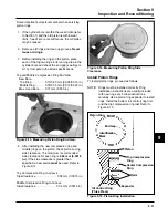
3. Pull the exhaust side cam shaft and slotted thrust
washer, out of the crankcase. See Figure 8-41.
Disassemble Closure Plate
1. Remove the governor gear and regulating pin
assembly. Gently pry upward using the blades of
two small screwdrivers. See Figure 8-37.
NOTE: The governor gear is held onto the shaft by
small molded tabs in the gear. When the gear
is removed these tabs are destroyed and the
gear must be replaced. Governor gear
removal is required for closure plate
disassembly and cleaning of the oil passages.
NOTE: The ACR weight and spring normally captured
by the thrust washer and installation of
closure plate, will fall out if the exhaust cam
gear is turned upside down.
Figure 8-38. Removing Oil Passage Cover and
Gasket.
Remove Cam Gears, Cam Shafts, and Oil
Pump
1. Remove the thrust washers and cam gears from
the cam shafts. See Figure 8-39.
Figure 8-37. Removing Governor Gear.
2. Remove the six screws securing the oil passage
cover to the closure plate. Remove the cover and
gasket. See Figure 8-38.
Figure 8-39. Removing Cam Gears.
2. Remove the screws securing the cam levers to
the crankcase. See Figure 8-40. Mark the cam
levers for proper reassembly.
Содержание Kohler SV470
Страница 1: ...Workshop manual Kohler Courage Tractor Engines English ...
Страница 3: ......
Страница 17: ...1 14 Section 1 Safety and General Information ...
Страница 43: ...5 16 Section 5 Fuel System and Governor ...
Страница 93: ...9 14 Section 9 Inspection and Reconditioning ...
Страница 116: ...2004W27 114 03 04 26 ...


