


10.10
Section 10
Reassembly
Figure 10-36. Cylinder Head Fastener Torque
Sequence.
Install Rocker Arms and Push Rods
NOTE: Installation and seating of the push rods into
the cam lever recesses during this
sequence is critical. Position the engine with
the cylinder head up if possible, to aid with
proper installation of the push rods and rocker
arms, and adjusting the valve lash.
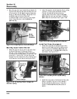
1. Position the push rod guide plates on the cylinder
head with the extruded edges down over the
push rod bores. Secure by installing the rocker
arm pivot studs. Torque the studs to
13.5 N·m
(120 in. lb.)
. See Figure 10-37.
5
1
4
3
2
6
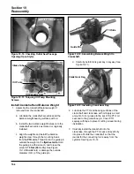
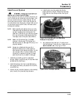
Figure 10-33. Installing Drain Back Check Ball.
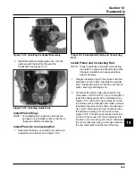
4. Install a new cylinder head gasket. See Figure
10-34.
IMPORTANT-
2. If the crankshaft has not been turned since the
installation of the crank gear, turn it one (1)
complete revolution. This will set the piston at
top dead center (TDC) of the compression
stroke, for proper valve lash adjustment later.
3. Install the drain back check ball into the keyhole
slot in the top of the crankcase. See Figure 10-33.
Figure 10-34. Installing Head Gasket.
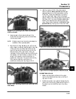
5. Install the cylinder head and start the six hex.
flange screws. Install the thick washer on the
screw closest to the exhaust port. See Figure
10-35.
Figure 10-35. Installing Cylinder Head Fasteners.
6. Using the torque sequence shown in Figure
10-36, torque the cylinder head screws in two
stages; initially to
20.5 N·m (180 in. lb.)
, and
finally to
41.0 N·m (360 in. lb.)
.
Washer
(Position 6)
Содержание Kohler SV470
Страница 1: ...Workshop manual Kohler Courage Tractor Engines English ...
Страница 3: ......
Страница 17: ...1 14 Section 1 Safety and General Information ...
Страница 43: ...5 16 Section 5 Fuel System and Governor ...
Страница 93: ...9 14 Section 9 Inspection and Reconditioning ...
Страница 116: ...2004W27 114 03 04 26 ...


