


10.17
Section 10
Reassembly
10
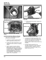
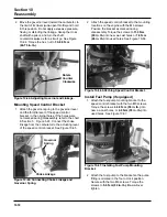
Figure 10-59. Air Cleaner Base Upper Mounting
Tab Details.
Figure 10-60. Installing Air Cleaner Base.
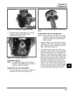
b.
Models with one screw and one mounting
stud only:
Apply hand pressure to keep the
parts from shifting, then carefully remove the
alignment pin and install DRY the long M6
thread forming screw DO NOT OIL. See
Figure 10-61. Check to make sure all
gaskets are still in proper position.
Figure 10-61. Installing Mounting Screw. (Models
with one stud and one screw).
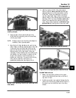
Tab on Top of Closure Plate
Figure 10-62. Torquing Air Cleaner Fasteners.
10. Attach the breather hose to the valve cover and
air cleaner base.
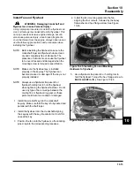
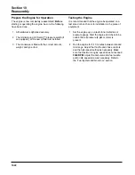
Install and Adjust Governor Lever
1. Install the governor lever* onto the governor shaft
with the lever section up. Connect the throttle
linkage using the black linkage bushing. See
Figure 10-63.
*NOTE: It is recommended that a new governor lever
be installed whenever removal is performed.
c. Torque the nut(s) to
5.5 N·m (48 in. lb.)
.
Torque the screw to
8.0 N·m (70 in. lb.)
into a
new hole, or
5.5 N·m (48 in. lb.)
into a used
hole,
do not
over tighten. See Figure 10-62.
The M6 screw for the upper tab will be
installed when the blower housing is mounted.
Figure 10-63. Governor Lever Installed on Shaft.
Содержание Kohler SV470
Страница 1: ...Workshop manual Kohler Courage Tractor Engines English ...
Страница 3: ......
Страница 17: ...1 14 Section 1 Safety and General Information ...
Страница 43: ...5 16 Section 5 Fuel System and Governor ...
Страница 93: ...9 14 Section 9 Inspection and Reconditioning ...
Страница 116: ...2004W27 114 03 04 26 ...