


9.13
Section 9
Inspection and Reconditioning
9
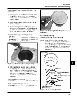
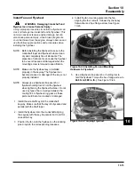
Procedure to Install Governor Shaft:
1. Install new pin by pressing or lightly tapping it into
the closure plate. It must be installed so that it
protrudes
44.50 mm (1.750 in.)
, plus or minus
0.101 mm (0.004 in.)
above the crankcase boss.
See Figure 9-19.
Governor Gear and Shaft
Inspection
Inspect the governor gear teeth. Look for any
evidence of worn, chipped, or cracked teeth. If one or
more of these problems is noted, replace the governor
gear.
The gear is held on the governor shaft by molded
tabs, which are damaged when the gear is removed.
Never reuse the gear once it has been pulled from the
shaft. Replace the governor shaft only if it is damaged
or worn.
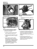
Procedure to Remove Governor Shaft:
1. Remove the blower housing, flywheel, and cooling
fan.
2. Remove the stator and crankshaft key.
3. Remove the closure plate screws and closure
plate.
4. Rotate engine to top dead center aligning timing
marks on the crankshaft and cam gears.
5. Remove the governor gear assembly and
regulating pin from the closure plate with two
small screwdrivers.
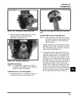
6. Locate the governor pin from flywheel side. With a
small punch, drive the pin out of the closure plate.
This could also be done with a press.
DO NOT
remove the governor pin with a vise grip or pliers,
you may damage the closure plate.
7. Remove any old gasket material from the mating
surfaces of the crankcase and closure plate. Use
an aerosol gasket remover to help loosen any old
gasket material.
Do not
scrape the surfaces, as
any scratches, nicks, or burrs can result in leaks.
Governor Gear
Shaft
*To Gasket Surface - Before Oil Passage
Cover Plate and Gasket are Assembled
44.50 mm
(1.750 in.)*
Figure 9-19. Governor Shaft Press Depth.
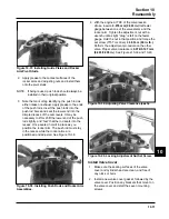
2. Install the new governor regulating pin and
governor gear assembly.
3. Make sure governor gear assembly rotates freely.
4. Check that timing marks are still aligned.
5. Install a new closure plate gasket and install the
closure plate. Refer to Reassembly Section 10
for proper torque sequence and specification.
6. Complete engine reassembly following
Reassembly procedures.
7. When engine reassembly is completed, reset
initial governor adjustment according to
procedure in Fuel System and Governor
Section 5.
Содержание Kohler SV470
Страница 1: ...Workshop manual Kohler Courage Tractor Engines English ...
Страница 3: ......
Страница 17: ...1 14 Section 1 Safety and General Information ...
Страница 43: ...5 16 Section 5 Fuel System and Governor ...
Страница 93: ...9 14 Section 9 Inspection and Reconditioning ...
Страница 116: ...2004W27 114 03 04 26 ...


