UO-EPB-1
Operating and configuration instructions
28
UO-EPB1_Manual-en_R1
9 Documents
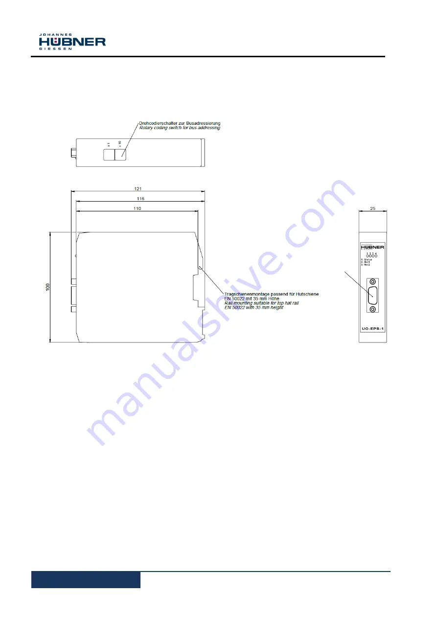
9.1 Dimensional drawing, wiring diagram
PROFIBUS D-SUB 9
Страница 1: ...6611 Operating and configuration instructions UO EPB 1 PROFIBUS module PROFIBUS DP interface U ONE LWL Universal encoder system Generation II Read the operating and assembly manual before assembly before starting installation and before completing all other work Store the manual for future use ...
Страница 2: ...ct names are trademarks or registered trademarks of their respective owners Protected trademarks or are not always designated as such in this manual However this does not mean that they may be used freely Copyright protection This operating and assembly manual including the figures it contains are copyright protected Third party usage of this operating and assembly manual in deviation from copyrig...
Страница 3: ...n module 9 3 4 Type plate 10 3 5 Electrical data 10 4 Commissioning 10 4 1 User manual 10 4 2 Profibus profile of the module 11 4 3 Bus addressing 12 4 4 Connecting the module to the Profibus 12 4 5 Configure the module 13 4 6 Configuring the module 13 4 7 Configuration in hex code 14 4 8 Operating the module in the Hübner 2 1 and Hübner 2 2 profiles 14 4 9 Desired resolution 15 4 9 1 Desired reso...
Страница 4: ...ages 24 6 1 Operating statuses and displays 25 6 1 1 Bus status 25 6 1 2 Status LED 26 7 Inspections 26 8 Transportation packaging and storage 26 8 1 Transportation safety information 26 8 2 Incoming goods controlling 26 8 3 Packaging disposal 26 8 4 Storing packages devices 26 8 5 Returning equipment repair goodwill warranty 27 8 6 Disposal 27 9 Documents 28 9 1 Dimensional drawing wiring diagram...
Страница 5: ...is included in the scope of delivery for the function mod ule The scope of delivery for the EPB also includes the software support CD 1 3 Explanation of symbols Warning information is designated using symbols Information is proceeded by signal words which express the extent of the danger involved Always comply with these notices and use cau tion to avoid accidents personal injury and property dama...
Страница 6: ...ach in the area where the function module is used In addition to the operating and configuration manual general statutory and other binding regulations on accident prevention and environmental protection must be observed Opera tors must be trained on these regulations Applicable national local and system specific provisions and requirements must be ob served The operator is obligated to inform per...
Страница 7: ...ances necessary to carry out the required work and who have been authorised to do so by the persons responsible for the safety of the system They are able to identify and avoid po tential hazards In addition please see standards VDE 0105 100 and IEC 364 for the definition of qualified personnel reference e g Beuth Verlag GmbH VDE Verlag GmbH Responsibilities for assembly installation commissioning...
Страница 8: ...ctrical connections when the module is powered down Review any potential hazards due to interactions with other systems and devices currently installed in the surrounding area or which are to be installed The user is responsible for taking relevant measures Cables used must be suitable for the temperature range Defective function modules may not be operated Opening function modules is prohibited T...
Страница 9: ...d shaft drive In general the requirements and acceptance conditions for the system as a whole must be observed 3 2 Basic regulations WARNING Power and signal lines must be installed separately Observe the manufacturer s information when installing converters shielding on power lines between the frequency converter and motor Ensure the energy supply is sufficient for the application 3 3 Replacing t...
Страница 10: ...issioning 4 1 User manual The module transmits the Multiturn and Singleturn absolute value for the basic device It can be configured in profiles CLASS 1 Hübner 1 0 with configuration of the counting direction and CLASS 2 Hübner 2 0 with the additional setting for resolution revolution and the overall resolu tion The profiles Hübner 2 1 and Hübner 2 2 are also available These also provide the follo...
Страница 11: ... the scaling function on off Resolution rotation Total resolution HÜBNER 2 1 Single Multiturn Like HÜBNER 2 0 in addition Desired measurement steps Desired resolution per revolution maximum total resolution physical measurement steps Switching the commissioning module on off Set preset value and change counting direction in online mode Determine gear factor scale Switch lower limit switch on off L...
Страница 12: ...the GSD file into the GSD directory of the COM PROFIBUS software Then start the COM PROFIBUS installation software Create a new configuration file using the NEW menu item under the FILE menu or access a configuration file via the OPEN menu item Then read in the GSD file in the menu item READ IN GSD FILES Now search for type IM308C under the DP master and search for HÜBNER encoder AMP1212 under DP ...
Страница 13: ...d bytes 4 6 Configuring the module In this example the Configure window shows the setting options for an absolute encoder config ured as HÜBNER 2 0 NOTE If the class 2 function is switched off then the module will work in HÜBNER 1 0 mode In this case only the counting direction can be changed The resolution per revolution can be any value between 1 and 4096 and deter mines the step length The tota...
Страница 14: ...set should then be reset in normal op eration since it refers to the scaled values 4 7 Configuration in hex code The configuration can also be carried out in the HEX CONFIGURE window However this is time consuming and requires a precise knowledge of the functions of the individual bits and bytes 4 8 Operating the module in the Hübner 2 1 and Hübner 2 2 profiles These two profiles have some additio...
Страница 15: ... purpose 8 steps should then be entered in the desired measurement step and 64 steps in total resolution NOTE The number of revolutions must have a value of 2n with n 1 12 Failure to observe these requirements will cause the output position values to be am biguous since the transition from the maximum basic device position to the position value of 0 will then always be completed at different basic...
Страница 16: ...ioning mode If this mode is activated the following functions are available in online mode Changing the counting direction Setting the preset value Automatic scaling teach in These values are set by the Profibus master by manipulating the status bit in DDLM_DATA_EX CHANGE mode A more detailed description is provided in a later section 4 11 Limit switch There are two software limit switches availab...
Страница 17: ...tinued operation in DDLM_Data_Exchange mode Settings for the required functions are set first via selection menus in Profibus system windows COMProfibus In some cases however it is necessary to know the commands used for this purpose in order to change parameters manually 5 1 Configuring and parameterising the module The following section describes which bits can be set in DDLM_SET_PRM mode Octets...
Страница 18: ...g from the maximum position to the position 0 and the position data will no longer be unambigu ous 5 1 2 DDLM_Set_Prm Modus for Hübner 2 1 and Hübner 2 2 The user profiles HÜBNER 2 1 and HÜBNER 2 2 are a supplement to the CLASS 2 profile They offer additional functions the user can take advantage of Unused functions can be switched off Online configuration in DDLM_DATA_EXCHANGE mode is possible to...
Страница 19: ... bit is used to release other module functions available in this profile in Octet 26 5 1 2 2 Measurement steps per xxx Octet 10 13 desired measurement steps Octet 26 0 26 1 The bits for the desired measurement steps Octet 26 0 and 26 1 can be used to save a value in Octet 10 13 that refers to the following ranges Measurement steps per revolution Measurement steps per max total resolution Physical ...
Страница 20: ...mode should be switched off 5 1 2 4 Reduced diagnostics Octet 26 4 Some Profibus masters generally older ones cannot receive all diagnostic bytes of the module See the documentation for the master used When the bit is set only 16 diagnostic bits are transferred 5 1 2 5 Octet 27 39 active Octet 26 7 If this bit is set it provides access to Octets 27 39 This releases the functions limit switch min a...
Страница 21: ...aning Bit 25 0 angular encoder not ready for oper ation 1 angular encoder ready for operation Bit 26 0 commissioning mode 1 normal mode Bit 27 0 software limit switch min actual process value max 1 software limit switch min actual process value max Bit 28 0 counting direction clockwise Looking towards end of shaft 1 counting direction anti clockwise Looking towards end of shaft Bit 31 0 normal ope...
Страница 22: ...TE The preset value must be reset after setting the direction of rotation 5 2 3 Scaling the module in the teach in process This process makes it possible to automatically scale the module After starting the process the system is moved along a defined path Then after the process is stopped the number of steps into which the travelled path should be divided is input The path of travel may not exceed...
Страница 23: ...n into consideration in the scaling ATTENTION The number of desired steps may not exceed the physical resolution in the path of travel Ensure the counting direction bit 28 is correct It may need to be reset after this function Since the preset value was deleted when scaling was started it must be reset in another step Scaling is stored in the module in a failsafe manner To continue using the scali...
Страница 24: ... Profi bus stand ard 1 4 Diagnostic Master Add 1 5 6 PNO number 15 0 PNO number of the encoder 1 7 Expanded diagnostic header Number of diag nostic bytes 1 8 Alarm mes sage 4 EEProm memory error 1 error 1 9 Operating status 0 1 2 3 Direction Class 2 function Diagnostic routine Scaling function 0 CW 1 CCW 0 Off 1 On 0 Off 1 On 0 Off 1 On 1 10 Encoder type 1 Single Multiturn Singleturn 0 Multiturn 1...
Страница 25: ...et2 LEDs are on the front panel of the module housing They are used to display the current module status 6 1 1 Bus status Net1 red Net2 green Error message bus status off off No power supply on on Wait for configuration by the master e g incorrect wiring terminal resistance set incorrectly on flashing Coding and or configuration error such as data length too great total resolution too high on off ...
Страница 26: ...amage due to improper transportation These symbols and information on the packaging must be observed Do not throw risk of breakage protect against wetness 8 2 Incoming goods controlling The delivery must be checked promptly for transportation damage and to ensure it is complete upon receipt If there is transportation damage the carrier must be informed directly upon delivery take photos as evidenc...
Страница 27: ...s that have come into contact with radioactive radiation or materials will not be taken back Devices that have come into contact with biological or chemical substances that could be hazard ous to health must be decontaminated before they are returned A clearance certificate must be enclosed 8 6 Disposal The manufacturer is not obligated to take back the devices The EPB must be treated as special e...
Страница 28: ...UO EPB 1 Operating and configuration instructions 28 UO EPB1_Manual en_R1 9 Documents 9 1 Dimensional drawing wiring diagram PROFIBUS D SUB 9 ...