l
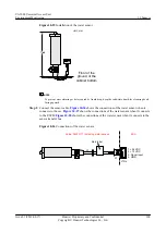
Install the sensor against the wall, with a distance of 1.5 m above the ground.
l
Install the sensor in a position where the air flows smoothly, with the flowing speed in the
range of 0.1 m/s to 1m/s.
l
Do not install the sensor in the following situations:
–
The relative humidity is higher than 90% RH for a long period.
–
The temperature is lower than -20°C.
–
Cold or hot wind can blow to the sensor.
–
There is corrosive air, such as sour gas and oil gas, or the air is polluted.
–
Those corners in which the air cannot flow smoothly.
–
The places in which the air flows too quickly, such as the ventilation window of the
room, and the ventilation holes of the air conditioner.
l
Do not install the sensor to the wiring trough end.
Precautions
l
Ensure the installation surface is clean.
l
Turn off the power during installation and replacement.
l
Do not drill holes around the installed sensors because the dust generated in drilling may
affect the sensor functions. If you do need to drill holes around the installed sensors, adopt
protection measures.
l
Do not touch the humidity-sensible components with your hands.
l
Exercise care when taking box cover, circuit board and connecting cables so as to avoid
mechanical damage.
l
To take the circuit board, hold the edges at two sides of the board, and do not touch the
components to so as to avoid pin bending or ESD damage to the components.
l
Put the removed circuit board to a clean place.
Procedure
Step 1
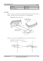
Remove the backplane from the temperature and humidity sensor, and you will see three
installation holes on the backplane. Mark holes on the wall by using a pencil.
Step 2
Select a Ф6 bit, and use the drill to drill holes at the marked positions on the wall.
Step 3
Insert the plastic expansion tube M6 x 26 into the installation hole.
Step 4
Use the M2 tapping screw to fix the temperature and humidity sensor against the wall.
Step 5
Install the main body of the temperature and humidity sensor to the backplane.
Step 6
monitoring cables used by the temperature and humidity sensor.
NOTE
In the above figures, JTAx refers to the analog parameter port on the ESC, which is determined by the main
label on the monitoring cable. Insert the monitoring cable to the corresponding analog port.
UA5000 Universal Access Unit
Environment Monitoring
10 Sensors
Issue 01 (2012-08-17)
Huawei Proprietary and Confidential
Copyright © Huawei Technologies Co., Ltd.
194

