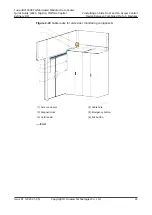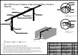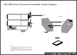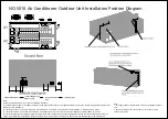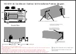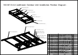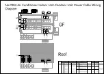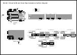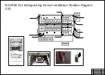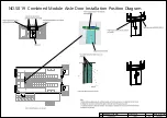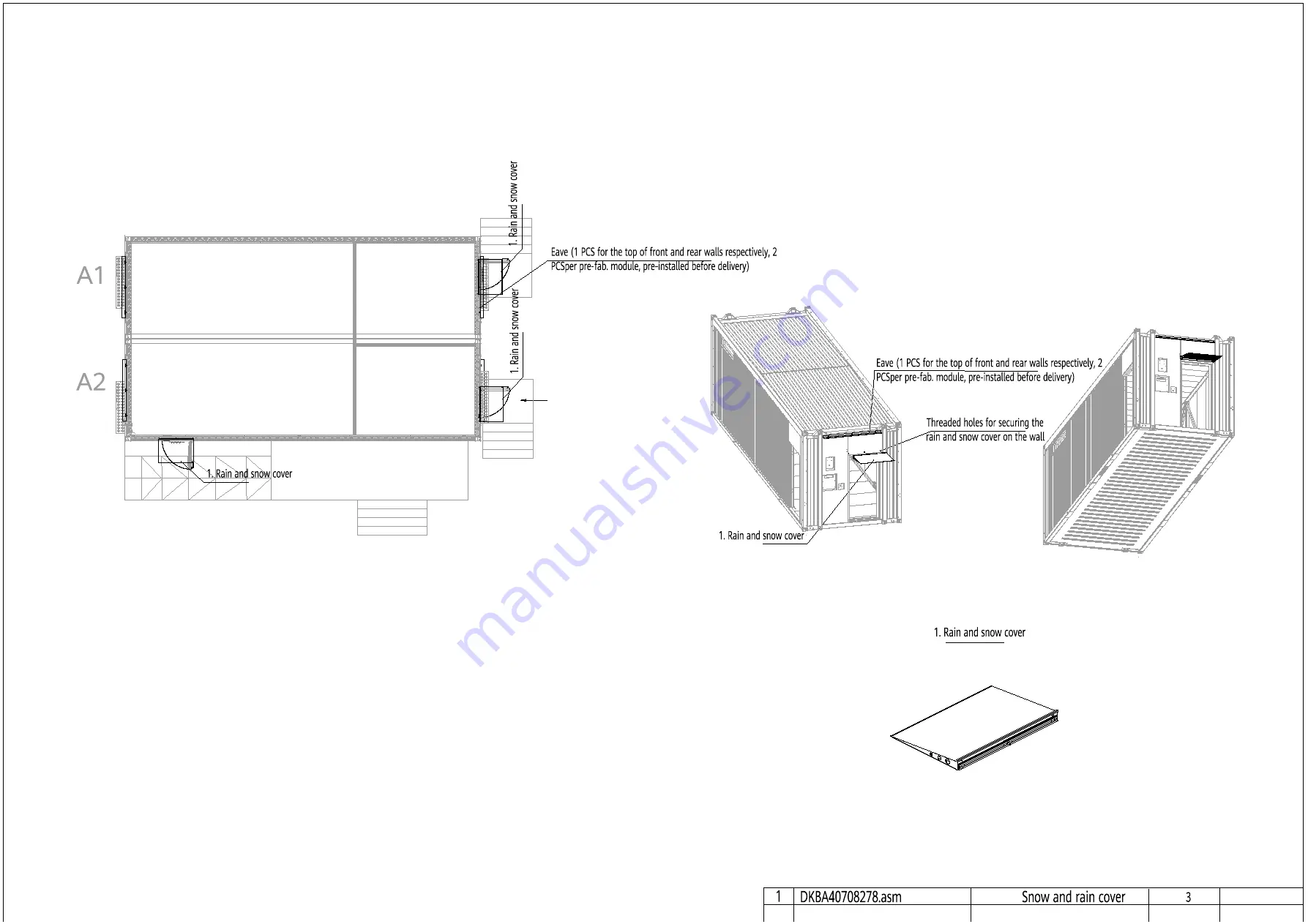
NO.S009 External Accessories Installation Position Diagram
Enlarged at 4:1
Note:
1. Secure the eaves to the top of the front and rear walls using
M16 bolts delivered with the eaves.
2. Install the snow and rain cover on the mounting plate above
the fireproof door, and then secure the cover on the mounting
plate.
(A direction)
A
25
26
27
28
29
30
31
32
33
34
25
26
27
28
29
30
31
32
33
34
25
26
27
28
29
30
31
32
33
34
25
26
27
28
29
30
31
32
33
34
No. Drawing No.
Item
Qty
Remarks
Содержание FusionDC1000B
Страница 45: ......
Страница 46: ......
Страница 51: ......
Страница 52: ......
Страница 53: ......
Страница 54: ......
Страница 55: ......
Страница 56: ......
Страница 59: ......
Страница 60: ......
Страница 61: ......
Страница 68: ......
Страница 69: ......
Страница 70: ......
Страница 71: ......
Страница 72: ......
Страница 73: ......
Страница 77: ......
Страница 82: ......
Страница 83: ......
Страница 92: ......
Страница 93: ......
Страница 94: ......
Страница 98: ...Window CB DH 1 Window CB PR B1 ECC NO M001 Monitoring Device Layout Diagram ...
Страница 110: ...NO F002 Fire Extinguishing System Conceptual Diagram CE ...
Страница 111: ...NO F002 Fire Extinguishing System Conceptual Diagram CE ...
Страница 112: ...NO F002 Fire Extinguishing System Conceptual Diagram CE ...
Страница 113: ...NO F002 Fire Extinguishing System Conceptual Diagram CE ...
Страница 114: ...NO F002 Fire Extinguishing System Conceptual Diagram CE ...
Страница 115: ...NO F002 Fire Extinguishing System Conceptual Diagram CE ...
Страница 116: ...NO F002 Fire Extinguishing System Conceptual Diagram CE ...
Страница 117: ...NO F002 Fire Extinguishing System Conceptual Diagram CE ...
Страница 118: ...NO F002 Fire Extinguishing System Conceptual Diagram CE ...
Страница 119: ......
Страница 120: ...Window CB DH 1 Window CB PR B1 EXIT Exit DH 3 NO F003 Emergency Exit Diagram ...

