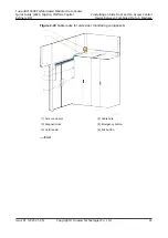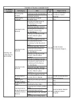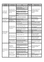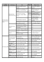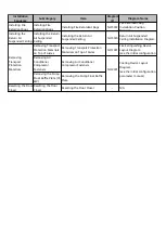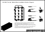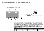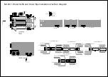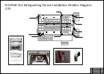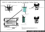
NO.S004 Pre-fab. Module Combining Position Diagram
Note:
1. Before combining pre-fab. modules, remove the transport side walls, and then install
combination distance blocks and front distance blocks.
2. Before combining pre-fab. modules, install combination distance blocks and front distance
blocks. After combining pre-fab. modules, remove the front distance blocks.
3. Each pre-fab. module combination position has four combination distance blocks.
4. Remove the transport side walls as follows:
1). Remove the edge wraps (marked 4 in the figure) from the side edge of the right panel
(marked 5 in the figure).
2). Remove the rightmost EPS panel (marked by 5 in the figure), and then remove the
remaining EPS panels in sequence according to the removal direction shown in the figure.
3). Remove the remaining edge wraps (marked 6 in the figure) of the transport side wall, and
then remove the remaining beams and columns (marked 7 in the figure) of the transport side
wall.
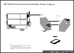
2. Front distance block
Enlarged at 10:1
1. Side combination
distance block
Enlarged at 10:1
1. Combination distance block (4 PCS/module)
Remove the transport side wall (11 EPS panels) at the module combination position
2. Front distance block (1 PCS/module)
Screw assembly M10X40
Removal direction
1. Combination distance block
2. Front distance block
1. Combination distance block
DKBA80912330 (300X150X25)
1
Combination distance block
DKBA80897988 (200X50X25)
4
Front distance block
No.
Drawing No.
Item
Qty
Remarks
1
2
Screw assembly M10X40
7
3
GB9074_17-88_M10X40_S_ZNAL
Содержание FusionDC1000B
Страница 45: ......
Страница 46: ......
Страница 51: ......
Страница 52: ......
Страница 53: ......
Страница 54: ......
Страница 55: ......
Страница 56: ......
Страница 59: ......
Страница 60: ......
Страница 61: ......
Страница 68: ......
Страница 69: ......
Страница 70: ......
Страница 71: ......
Страница 72: ......
Страница 73: ......
Страница 77: ......
Страница 82: ......
Страница 83: ......
Страница 92: ......
Страница 93: ......
Страница 94: ......
Страница 98: ...Window CB DH 1 Window CB PR B1 ECC NO M001 Monitoring Device Layout Diagram ...
Страница 110: ...NO F002 Fire Extinguishing System Conceptual Diagram CE ...
Страница 111: ...NO F002 Fire Extinguishing System Conceptual Diagram CE ...
Страница 112: ...NO F002 Fire Extinguishing System Conceptual Diagram CE ...
Страница 113: ...NO F002 Fire Extinguishing System Conceptual Diagram CE ...
Страница 114: ...NO F002 Fire Extinguishing System Conceptual Diagram CE ...
Страница 115: ...NO F002 Fire Extinguishing System Conceptual Diagram CE ...
Страница 116: ...NO F002 Fire Extinguishing System Conceptual Diagram CE ...
Страница 117: ...NO F002 Fire Extinguishing System Conceptual Diagram CE ...
Страница 118: ...NO F002 Fire Extinguishing System Conceptual Diagram CE ...
Страница 119: ......
Страница 120: ...Window CB DH 1 Window CB PR B1 EXIT Exit DH 3 NO F003 Emergency Exit Diagram ...


