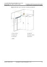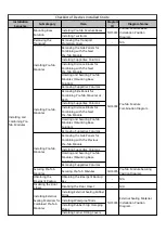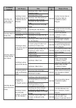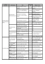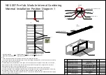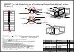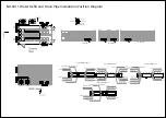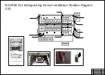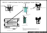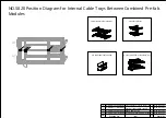
NO.S007 Pre-fab. Module Internal Combining Material Installation Position
Diagram-3
Note:
1. Install the end module combination materials in the following sequence:
(1) Insert the Armaflex thermal insulation pipe.
(2) Use the end edge wrap to secure the rock wool,and apply glue to secure it at the position shown
in the figure.
(3) Install the thermal insulation foam in the edge wrap groove.
(4) Install the end at the module combination position on the end wall.
(5) Install the rock wool panel on the partition wall, as shown in the figure. Place the entire rock
wool panel from the front wall side, and install the front and rear flat buckles and internal corners.
(5) Install the internal corners, baseboards, and flat buckles as shown in the figure.
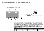
(6) After installing all internal sealing kits, ground the pre-fab. modules by referring to NO.S008
Pre-fab. Module Grounding Position Diagram.
Install Armaflex
thermal insulation pipe
Install end wall
rock wool
Install partition
wall rock wool
A
End internal sealing
A enlarged view
3. Rock wool 1
1.Armaflex thermal insulation pipe
2. Edge wrap
Edge wrap
B
B enlarged view
Rock wool 1
End thermal insulation foam
Armaflex thermal insulation pipe
Edge wrap
6. Internal corner
No.
Drawing No.
Item
Qty Remarks
1
2
3
4
5
6
7
8
DKBA80998528.ASM
8
Armaflex thermal insulation pipe
2
DKBA04851489_F_327X3079X25_C0
1
DKBA04851489_F_3080X394X100
3
DKBA82064398.ASM
End thermal insulation foam
Rock wool 1
Rock wool 2
DKBA61589565.ASM
1
Baseboard1
DKBA61613971.ASM
2
Baseboard2
DKBA04853355-A03R03_2950_KP5
2
Internal corner
9
DKBA82064397.ASM
3
Edge wrap
4. Rock wool 2
5. End thermal
insulation foam
8. Baseboard1
9. Baseboard 2
DKBA04853355-A03R01_2950
3
Flat buckle
7. Flat buckle
Install baseboard, internal
corner, and flat buckle
Attach the end edge wrap to rock
wool using structural adhesive
Attach the end edge wrap to rock
wool using structural adhesive
4. Rock wool 2
Install the whole rock wool from this side.
Содержание FusionDC1000B
Страница 45: ......
Страница 46: ......
Страница 51: ......
Страница 52: ......
Страница 53: ......
Страница 54: ......
Страница 55: ......
Страница 56: ......
Страница 59: ......
Страница 60: ......
Страница 61: ......
Страница 68: ......
Страница 69: ......
Страница 70: ......
Страница 71: ......
Страница 72: ......
Страница 73: ......
Страница 77: ......
Страница 82: ......
Страница 83: ......
Страница 92: ......
Страница 93: ......
Страница 94: ......
Страница 98: ...Window CB DH 1 Window CB PR B1 ECC NO M001 Monitoring Device Layout Diagram ...
Страница 110: ...NO F002 Fire Extinguishing System Conceptual Diagram CE ...
Страница 111: ...NO F002 Fire Extinguishing System Conceptual Diagram CE ...
Страница 112: ...NO F002 Fire Extinguishing System Conceptual Diagram CE ...
Страница 113: ...NO F002 Fire Extinguishing System Conceptual Diagram CE ...
Страница 114: ...NO F002 Fire Extinguishing System Conceptual Diagram CE ...
Страница 115: ...NO F002 Fire Extinguishing System Conceptual Diagram CE ...
Страница 116: ...NO F002 Fire Extinguishing System Conceptual Diagram CE ...
Страница 117: ...NO F002 Fire Extinguishing System Conceptual Diagram CE ...
Страница 118: ...NO F002 Fire Extinguishing System Conceptual Diagram CE ...
Страница 119: ......
Страница 120: ...Window CB DH 1 Window CB PR B1 EXIT Exit DH 3 NO F003 Emergency Exit Diagram ...

