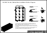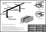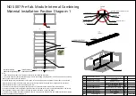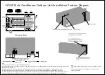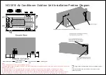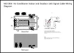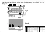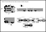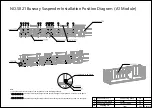
NO.S010 Air Conditioner Outdoor Unit Installation Position Diagram
Note:
1. This figure shows the installation of the air conditioner outdoor
unit.
2. Secure the outdoor unit to the ground. For details, see the
outdoor unit guide.
Note:
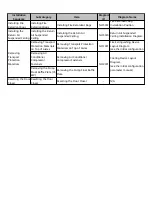
Install the outdoor unit on the top in the following sequence:
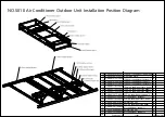
(1) Assemble the outdoor unit support, as shown in the figure about outdoor unit support assembly. Secure the support using stainless steel screws
(GB9074_17-88_M10X30_S).
(2) Install the outdoor unit on the top of the pre-fab. module and secure it using stainless steel (GB9074_17-88_M10X30_S)) screws.
(3) Install the outdoor unit at the position shown in the figure, and secure it using stainless steel (GB9074_17-88_M10X30_S)) screws.
(4) Install outdoor pipes. Bind copper pipes at the pre-fab. module outlet along the cable binding plate on the rear wall of the module, bind the
copper pipes along the cable binding plate on the lower layer of the outdoor unit support, and connect the copper pipes to the outdoor unit.
Assemble support
Install support on
module top
Install outdoor
unit
Install pipes
Содержание FusionDC1000B
Страница 45: ......
Страница 46: ......
Страница 51: ......
Страница 52: ......
Страница 53: ......
Страница 54: ......
Страница 55: ......
Страница 56: ......
Страница 59: ......
Страница 60: ......
Страница 61: ......
Страница 68: ......
Страница 69: ......
Страница 70: ......
Страница 71: ......
Страница 72: ......
Страница 73: ......
Страница 77: ......
Страница 82: ......
Страница 83: ......
Страница 92: ......
Страница 93: ......
Страница 94: ......
Страница 98: ...Window CB DH 1 Window CB PR B1 ECC NO M001 Monitoring Device Layout Diagram ...
Страница 110: ...NO F002 Fire Extinguishing System Conceptual Diagram CE ...
Страница 111: ...NO F002 Fire Extinguishing System Conceptual Diagram CE ...
Страница 112: ...NO F002 Fire Extinguishing System Conceptual Diagram CE ...
Страница 113: ...NO F002 Fire Extinguishing System Conceptual Diagram CE ...
Страница 114: ...NO F002 Fire Extinguishing System Conceptual Diagram CE ...
Страница 115: ...NO F002 Fire Extinguishing System Conceptual Diagram CE ...
Страница 116: ...NO F002 Fire Extinguishing System Conceptual Diagram CE ...
Страница 117: ...NO F002 Fire Extinguishing System Conceptual Diagram CE ...
Страница 118: ...NO F002 Fire Extinguishing System Conceptual Diagram CE ...
Страница 119: ......
Страница 120: ...Window CB DH 1 Window CB PR B1 EXIT Exit DH 3 NO F003 Emergency Exit Diagram ...

