10
Spark Ignition
The burner flame is ignited by applying high voltage to the system spark electrode. This causes a spark
from electrode to ground.
Outdoor Sensor
The outdoor sensor monitors outdoor temperature and adjusts the set point to provide greater efficiency.
Water temperature over 125
o
F can instantly cause severe burns, or death, from scalds. Children,
disabled, and elderly are at the highest risk of being scalded. See instruction manual before
setting temperature at water heater. Feel water before bathing or showering! Temperature limiting
valves are available.
PART 3 – PREPARE WATER HEATER LOCATION
Before considering location, many factors need to be addressed. Piping, Venting, and Condensation
Removal are just a few of the issues that need attention prior to the installation of the heater. Please read
the entire manual, as it could save time and money.
A. BEFORE LOCATING THE HEATER
Check for nearby connections to:
•
System water piping
•
Venting connections
•
Gas supply piping
•
Electrical power
•
Condensate drain
Check area around heater. Remove any combustible materials, gasoline, and other flammable liquids.
Failure to keep heater area clear and free of combustible materials, liquids, and vapors can result in
substantial property damage, severe personal injury, or death.
The heater gas control system components must be protected from dripping or spraying water during
operation and service.
If replacing an existing heater, check for and correct any existing system problems, such as:
•
System leaks
•
Heater is located in a condition that could cause the system to freeze and leak.
•
Incorrectly-sized expansion tank
•
Clean and flush existing system when reinstalling a heater.
B. LEVELING
In order for the condensate to properly flow out of the collection system, the area where you locate the
heater must be level. Location must also fully support the weight of the filled water heater.
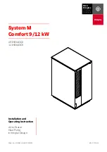
Содержание Versa Hydro PHE130-119
Страница 23: ...23 Figure 5 Figure 6 ...
Страница 24: ...24 Figure 7 ...
Страница 25: ...25 F HYDRONIC PIPING Figure 8 ...
Страница 26: ...26 Figure 9 ...
Страница 27: ...27 Figure 10 ...
Страница 28: ...28 Figure 11 ...
Страница 29: ...29 Figure 12 ...
Страница 32: ...32 F INTERNAL WIRING Figure 14 Internal connection diagram ...
Страница 38: ...38 Figure 17 ...
Страница 48: ...48 Figure 25 ...
Страница 76: ...76 Figure 29 ...
Страница 77: ...77 Figure 30 ...
Страница 78: ...78 Figure 31 LP 314 G ...
Страница 79: ...79 Figure 32 ...
Страница 81: ...81 ...
Страница 82: ...82 ...
Страница 83: ...83 MAINTENANCE NOTES ...


