31
devices, the anticipator should be set to match the power requirements of those connected devices. Refer
to the instruction manuals of the connected devices for further information.
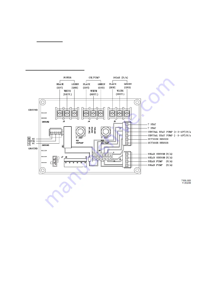
3. The
outdoor sensor
must be connected for the unit to operate at optimum efficiency. Use a minimum
22 AWG wire for runs of 100 feet or less and minimum 18 AWG wire for runs up to 150 feet. Instructions
are included with the outdoor sensor to correctly mount the sensor on the exterior surface of the building.
It is preferable to mount the sensor on the north side in an area that will not be affected by direct sunlight
but will be exposed to varying weather conditions. Connect the outdoor sensor to terminals marked
“Outdoor” in Figure 13.
E. FIELD CONNECTION BOARD
Figure 13 – Hydronic heating module
Содержание Versa Hydro PHE130-119
Страница 23: ...23 Figure 5 Figure 6 ...
Страница 24: ...24 Figure 7 ...
Страница 25: ...25 F HYDRONIC PIPING Figure 8 ...
Страница 26: ...26 Figure 9 ...
Страница 27: ...27 Figure 10 ...
Страница 28: ...28 Figure 11 ...
Страница 29: ...29 Figure 12 ...
Страница 32: ...32 F INTERNAL WIRING Figure 14 Internal connection diagram ...
Страница 38: ...38 Figure 17 ...
Страница 48: ...48 Figure 25 ...
Страница 76: ...76 Figure 29 ...
Страница 77: ...77 Figure 30 ...
Страница 78: ...78 Figure 31 LP 314 G ...
Страница 79: ...79 Figure 32 ...
Страница 81: ...81 ...
Страница 82: ...82 ...
Страница 83: ...83 MAINTENANCE NOTES ...


