HTP MIG 2400 Скачать руководство пользователя страница 9

9

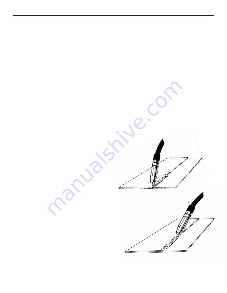
Figure 5 “Pulling the Weld”

Figure 4 “Pushing the Weld”

When tuning in your welding machine, it is best to start with 
the wire feed rate too high.  On the highest power setting, 
you may actually want to start with the wire feed rate set at 
maximum.  Gradually decrease the wire feed rate until the 
steady frying noise is heard.  A common problem many people 
have when trying to tun the wire feed rate is that they turn the 
knob too rapidly.  Many people never turn the wire feed rate 
down low enough and then start to increase it again.  If the 
wire feed rate is slowly decreased, then eventually you will 
cross the point where the machine will be tuned in.  It is a 
good idea to practice tuning in the welding machine.  Power 
setting #2, 3 is an ideal heat setting for this, as it has a nice, 
crisp sizzle.  Once you have mastered tuning in the machine 
on power setting #2, 3, practice tuning in the machine on 
different heat settings.

It is highly recommended that you practice with your welder 
at different power settings so that you will become familiar 
with your welder.  This is important to do prior to welding on 
a project so that you will know which heat setting to select for 
the job.

Seam Welding

Install the conical nozzle (Part #S4328) on the welding gun.  
The conical nozzle is used because it is much easier to see 
the welding process due to the taper in the nozzle.  Have 1/4" 
to 1/2" of welding wire protruding from the end of the gas 
nozzle.

Prior to running a seam weld, it is recommended that tack 
welds be placed every 2 to 3 inches along the seam, even 
closer for extremely thin panels.  Tack welds will help to hold 
the panel in place while welding, as well as to prevent panel 
separation caused by warpage.

Hold the welding gun at a 45-degree angle and use the edge 
of the gas nozzle to hold the two panels together, aim the 
welding wire at the spot to be tacked.  Momentarily press 
the trigger (approximately 1 second) and tack the two panels 
together.  Do not lift up the welding gun until the weld has set.  
Tack welding is done at the same power setting at which seam 
welding is done.  (1 or 2 on the course setting for sheet metal, 
3 or 4 for heavier material.)

When you have the panel tacked into place, you are ready to 
seam weld.  Once again, have 1/4" to 1/2" of welding wire 
protruding from the gas nozzle.  The welding gun is generally 
held at a 45-degree angle to the work piece.  It may also be 
tilted at a 45-degree angle to the side.  Rest the gun nozzle on 
the work piece and have the wire pointing at the spot where the 
welding is to begin.  Press the trigger and begin welding.  It is 
important that you can see the welding wire coming out of the 
gas nozzle and the small halo formed at the end of the welding 
wire where it is melting.  This halo will provide the light 
necessary to see through your helmet while welding.

The direction in which the welder travels will affect the 
characteristics of the weld.  When "pushing the weld" the 
welding gun is tilted away from the direction of travel (see fig. 
4).  When "pulling the weld" the welding gun is tilted toward 
the direction of travel (see fig. 5).

As you gain expertise with your welder, you will find that 
is possible to reduce warpage when welding sheet metal by 
welding at a higher power setting and moving faster along 
the seam.  In this way, you are reducing the amount of time 
welding, therefore reducing the amount of heat which is put 
into the panel.

Содержание MIG 2400

Страница 1: ...2400 Owner s Manual HTP America Inc 3200 Nordic Road Arlington Heights IL 60005 4729 1 800 USA WELD 847 357 0700 FAX 847 357 0744 www usaweld com Model 60240 24 America Inc...

Страница 2: ...in any event unless HTP America Inc receives notice of alleged breach of warranty within 30 days after the discovery actual or construction alleged breach of warranty specifying the claimed defect HT...

Страница 3: ...lose to degreasing or spraying operations Chlorinated hydrocarbon vapors may react with the ultra violet rays and form highly toxic phosgene gas If you develop momentary eye nose or throat irritation...

Страница 4: ...ed into the proper welding sound A hissing blowing sound with a ball of molten wire forming at the end of the wire and then dropping off indicates the wire feed rate is too slow A loud cracking noise...

Страница 5: ...s very similar to a lock on trigger on a drill or a grinder 7 Thermoswitch Indicator Light Your Mig 2400 has a duty cycle of 35 240 amps and 100 142 amps In the unlikely event you have welded long eno...

Страница 6: ...nd clamp be connected to a good clean surface Failure to do so will cause poor quality welds Place the ground clamp as close as possible to the area to be welded 14 Welding Gun Lead The welding gun le...

Страница 7: ...not enough pressure on the pressure roller Slowly tighten the pressure roller adjusting screw until the wire feeds evenly without slipping Then tighten an additional 1 4 turn for steel No additional t...

Страница 8: ...g beyond the weld and is not melting properly When tuned in properly a steady frying noise can be heard See Fig Z This means that the wire is melting properly and is melting right at the surface of th...

Страница 9: ...ll help to hold the panel in place while welding as well as to prevent panel separation caused by warpage Hold the welding gun at a 45 degree angle and use the edge of the gas nozzle to hold the two p...

Страница 10: ...Turn off the shield gas You are now ready to shrink Shrinking with your shrinking attachment is similar with any oxy acetylene torch the area is alternately heated and cooled until properly shrunk Th...

Страница 11: ...setting for hole filling is one to two settings below seam welding Welding Aluminum It is possible to weld aluminum with your MIG 2400 Depending on your application you may be able to get away with p...

Страница 12: ...d the metal and blow a big hole This is one of the problems of welding aluminum and just requires practice to overcome The end of the welding wire should always be clipped off with side cutters to aid...

Страница 13: ...posit a small puddle of molten wire on the stud and then allow it to cool Repeat the process until you have built up a small puddle of molten wire on the stud and allow it to cool Repeat the process u...

Страница 14: ...with spatter build up This nozzle is ruined because the operator allowed the spatter to build up excessively so the spatter has now welded itself to the inside of the gas nozzle Figures 11 and 12 sho...

Страница 15: ...330 Cylindrical Nozzle Aluminum Welding S4329 Spot Weld Nozzle Spot Welding 21 37F Small Conical Nozzle Tight Corners Changing the Drive Roll The drive roll has two grooves on it The narrower of the t...

Страница 16: ...e pressure roller has been adjusted too tightly When properly adjusted the drive roll will slip and bird nesting will never occur 16 Setting the Pressure on the Pressure Roller Prior to readjusting th...

Страница 17: ...welding gun Remove the liner positioner nut with a 12mm wrench and pull the old liner completely out of the welding gun See Fig 20 Remove the gas nozzle and contact tip If installing a Teflon liner i...

Страница 18: ...witch light will go out and the machine will be ready for use To keep the cooling system of your welder operating at peak performance it is necessary to remove the side panel and blow this area out wi...

Страница 19: ...a 1 8 40230 030 5356 Alloy Aluminum Wire 40230 4043 030 4043 Alloy Aluminum Wire Aluminum 16 ga 1 4 40235 035 5356 Alloy Aluminum Wire 40235 4043 035 4043 Alloy Aluminum Wire Stainless Steel 24 ga 1 8...

Страница 20: ...125 3 6 34 8 5 75 179 3 16 5 5 160 3 16 7 115 3 16 3 5 33 5 25 170 5 1 4 150 6 110 3 4 32 3 4 75 145 5 140 5 75 105 1 8 3 3 31 4 4 5 135 1 8 4 3 4 130 1 8 5 5 90 16 gauge 3 2 30 3 4 120 4 1 2 120 5 7...

Страница 21: ...21 HTP MIG 2400 Wiring Diagram...

Страница 22: ...22 Parts List MIG 2400...

Страница 23: ...2200 3 Fan 33 1 525014 0100 3 Fan Guard 34 1 706341 1701 1 Chain Illus Part Description 35 T1496004088 Wire Drive Brake Assy 37 3 2H0020 1789 0 Spacer 38 1 70C090 1010 1 Spindle Nut 40 1 506040 0330 3...

Страница 24: ...Nozzle Pkg 3 42 24108B Small Conical Nozzle Pkg 3 43 24106 Spot Weld Nozzle 50 24002 Swan Neck 56 15008 Handle Assy Blue Ergo does not include trigger Item Part Description 57 14009 Trigger 59 14018 S...

Страница 25: ...5 K61R Conductor Tube Retaining Nut 6 K81TWC Handle w Screws 7 K91 Trigger Switch w blades 8 K141 6 Cable Support Rubber 14 X040 Steel Liner 16 15041 Teflon Liner 16 19 K200 10E Power Cable 10 K200 1...

Отзывы: