HTP MIG 2400 Скачать руководство пользователя страница 18

18

Monthly Maintenance

Your HTP MIG Welder is a very hardworking piece of 
equipment and is very simple to maintain.  However, your 
HTP MIG Welder is more complicated than other types of 
welding equipment.  It is very important that these simple 
maintenance procedures be followed to keep your welder 
operating trouble free.

1. Wire Drive System

 – The guide tube and inlet wire guide 

should be check periodically to ensure that they are in correct 
alignment with the drive rolls.  Misalignment will result in 
the copper plating of the wire being rubbed off.  This copper 
dust will be carried into the liner resulting in increased friction 
causing wire feed problems.

2. Welding Cable

 – You should not allow heavy equipment to 

run over the welding cable.  Avoid pulling the machine by the 
cable.
Do not pull the welding cable over sharp edges.

3. Transformer and Internal Components

 – Your MIG 

2400 is equipped with a thermoswitch to protect the internal 
components of the machine should the duty cycle be 
exceeded.  The thermoswitch is placed in the low voltage 
circuit, so that when the duty cycle is exceeded, the main 
relay will not operate, preventing power from going to the 
main transformer, and the wire feed motor will not turn.  The 
indicator light will remain on, and the cooling fans will remain 
on.  The thermo indicator lamp will light up yellow, indicating 
the duty cycle has been exceeded.  When the machine cools 
down (approximately 20 minutes) the thermoswitch will 
automatically reset, the thermoswitch light will go out, and the 
machine will be ready for use.

To keep the cooling system of your welder operating at peak 
performance, it is necessary to remove the side panel and blow 
this area out with dry, compressed air.  This will remove dirt 
and dust from the internal components.

Sheild Gas

Since no flux is used for solid wire MIG welding, the proper 
shield gas must be used.  Different materials require different 
shield gases.  Use the chart below for a guide.


Material 

Shield Gas 

Flow Rate

Steel 

75% Argon - 25% CO2 

10 – 25 cfh

Aluminum 

100% Argon 

25 – 50 cfh

Stainless Steel 

90% 7.5% Argon – 2.5% CO2 

15 – 35 cfh

Brazing 

100% Argon 

15 – 35 cfh

Cast Iron 

75% Argon - 25% CO2 

25 – 35 cfh


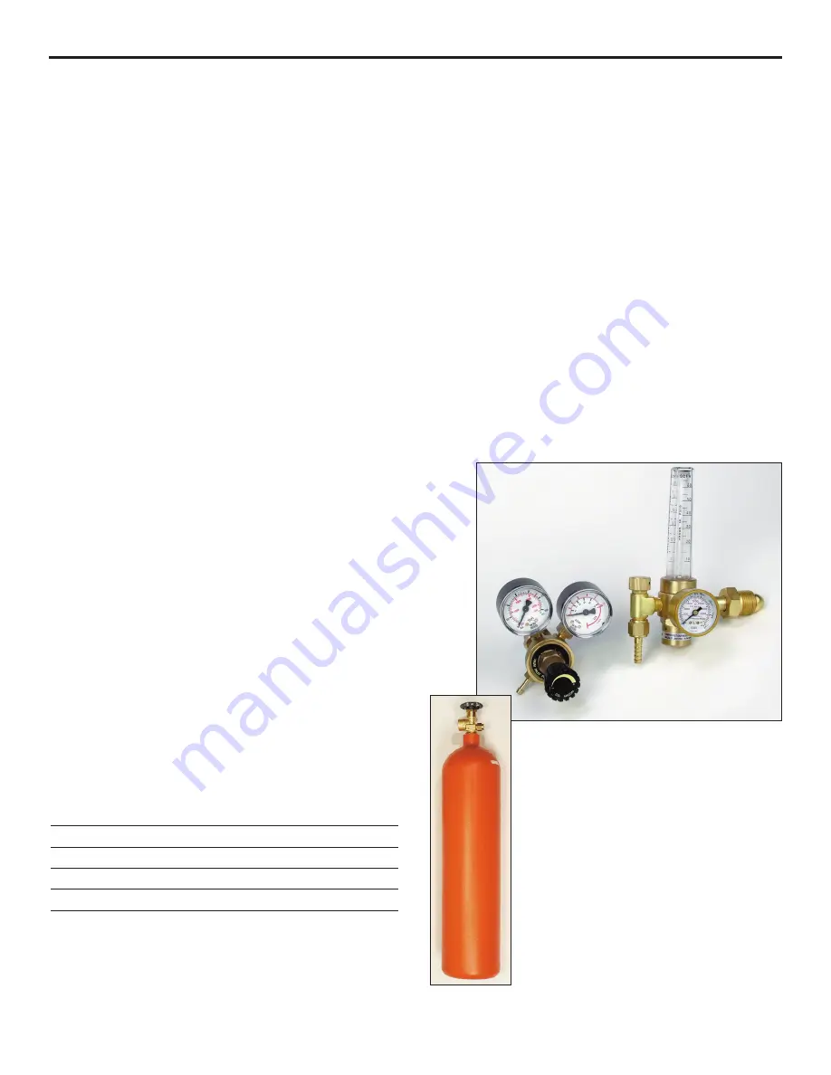
Use a gas regulator such as HTP Part #12020 or a flowmeter 
such as HTP Part # 12020F which is compatible with both 
Argon and C-25 gas cylinders and has a barbed fitting for the 
delivery hose.  Connect the gas hose to the brass fitting at the 
rear of the machine and to the barbed fitting on the regulator.

HTP also has available small 60 cubic foot gas bottles (Part 
#99900), which are ideal for use with your welder.  These 
bottles stand approximately 30" high and weigh less than 40 
pounds, making your welder very easy to move around the 
shop.  Be sure to check with your local gas supplier about 
filling these tanks before ordering.

If you already have a large cylinder, you can fill the small 
cylinder from the large cylinder using the transfer manifold 
(HTP Part #99905).

NOTE:  75% Argon – 25% CO2 may be used for stainless steel 
welding.  Stainless steel can also be welded with steel wire and 
75% Argon – 25% CO2 gas, however, these welds will not be as 
corrosion resistant as welds made with stainless steel wire.

12020

Gas 
Bottle

Содержание MIG 2400

Страница 1: ...2400 Owner s Manual HTP America Inc 3200 Nordic Road Arlington Heights IL 60005 4729 1 800 USA WELD 847 357 0700 FAX 847 357 0744 www usaweld com Model 60240 24 America Inc...

Страница 2: ...in any event unless HTP America Inc receives notice of alleged breach of warranty within 30 days after the discovery actual or construction alleged breach of warranty specifying the claimed defect HT...

Страница 3: ...lose to degreasing or spraying operations Chlorinated hydrocarbon vapors may react with the ultra violet rays and form highly toxic phosgene gas If you develop momentary eye nose or throat irritation...

Страница 4: ...ed into the proper welding sound A hissing blowing sound with a ball of molten wire forming at the end of the wire and then dropping off indicates the wire feed rate is too slow A loud cracking noise...

Страница 5: ...s very similar to a lock on trigger on a drill or a grinder 7 Thermoswitch Indicator Light Your Mig 2400 has a duty cycle of 35 240 amps and 100 142 amps In the unlikely event you have welded long eno...

Страница 6: ...nd clamp be connected to a good clean surface Failure to do so will cause poor quality welds Place the ground clamp as close as possible to the area to be welded 14 Welding Gun Lead The welding gun le...

Страница 7: ...not enough pressure on the pressure roller Slowly tighten the pressure roller adjusting screw until the wire feeds evenly without slipping Then tighten an additional 1 4 turn for steel No additional t...

Страница 8: ...g beyond the weld and is not melting properly When tuned in properly a steady frying noise can be heard See Fig Z This means that the wire is melting properly and is melting right at the surface of th...

Страница 9: ...ll help to hold the panel in place while welding as well as to prevent panel separation caused by warpage Hold the welding gun at a 45 degree angle and use the edge of the gas nozzle to hold the two p...

Страница 10: ...Turn off the shield gas You are now ready to shrink Shrinking with your shrinking attachment is similar with any oxy acetylene torch the area is alternately heated and cooled until properly shrunk Th...

Страница 11: ...setting for hole filling is one to two settings below seam welding Welding Aluminum It is possible to weld aluminum with your MIG 2400 Depending on your application you may be able to get away with p...

Страница 12: ...d the metal and blow a big hole This is one of the problems of welding aluminum and just requires practice to overcome The end of the welding wire should always be clipped off with side cutters to aid...

Страница 13: ...posit a small puddle of molten wire on the stud and then allow it to cool Repeat the process until you have built up a small puddle of molten wire on the stud and allow it to cool Repeat the process u...

Страница 14: ...with spatter build up This nozzle is ruined because the operator allowed the spatter to build up excessively so the spatter has now welded itself to the inside of the gas nozzle Figures 11 and 12 sho...

Страница 15: ...330 Cylindrical Nozzle Aluminum Welding S4329 Spot Weld Nozzle Spot Welding 21 37F Small Conical Nozzle Tight Corners Changing the Drive Roll The drive roll has two grooves on it The narrower of the t...

Страница 16: ...e pressure roller has been adjusted too tightly When properly adjusted the drive roll will slip and bird nesting will never occur 16 Setting the Pressure on the Pressure Roller Prior to readjusting th...

Страница 17: ...welding gun Remove the liner positioner nut with a 12mm wrench and pull the old liner completely out of the welding gun See Fig 20 Remove the gas nozzle and contact tip If installing a Teflon liner i...

Страница 18: ...witch light will go out and the machine will be ready for use To keep the cooling system of your welder operating at peak performance it is necessary to remove the side panel and blow this area out wi...

Страница 19: ...a 1 8 40230 030 5356 Alloy Aluminum Wire 40230 4043 030 4043 Alloy Aluminum Wire Aluminum 16 ga 1 4 40235 035 5356 Alloy Aluminum Wire 40235 4043 035 4043 Alloy Aluminum Wire Stainless Steel 24 ga 1 8...

Страница 20: ...125 3 6 34 8 5 75 179 3 16 5 5 160 3 16 7 115 3 16 3 5 33 5 25 170 5 1 4 150 6 110 3 4 32 3 4 75 145 5 140 5 75 105 1 8 3 3 31 4 4 5 135 1 8 4 3 4 130 1 8 5 5 90 16 gauge 3 2 30 3 4 120 4 1 2 120 5 7...

Страница 21: ...21 HTP MIG 2400 Wiring Diagram...

Страница 22: ...22 Parts List MIG 2400...

Страница 23: ...2200 3 Fan 33 1 525014 0100 3 Fan Guard 34 1 706341 1701 1 Chain Illus Part Description 35 T1496004088 Wire Drive Brake Assy 37 3 2H0020 1789 0 Spacer 38 1 70C090 1010 1 Spindle Nut 40 1 506040 0330 3...

Страница 24: ...Nozzle Pkg 3 42 24108B Small Conical Nozzle Pkg 3 43 24106 Spot Weld Nozzle 50 24002 Swan Neck 56 15008 Handle Assy Blue Ergo does not include trigger Item Part Description 57 14009 Trigger 59 14018 S...

Страница 25: ...5 K61R Conductor Tube Retaining Nut 6 K81TWC Handle w Screws 7 K91 Trigger Switch w blades 8 K141 6 Cable Support Rubber 14 X040 Steel Liner 16 15041 Teflon Liner 16 19 K200 10E Power Cable 10 K200 1...

Отзывы: