HTP MIG 2400 Скачать руководство пользователя страница 12

Shield Gas

 – The shield gas required for welding aluminum 

is 100% Argon.  Due to the rate at which aluminum oxidizes, 
the flow rate of the Argon gas must be increased to 25 cubic 
feet per hour (cfh) or more.  The cylindrical gas nozzle (Part 
#S4330) is recommended for use on the standard welding 
gun when welding aluminum.  The larger opening area of 
the nozzle will result in a wider dispersion of the shield gas, 
insuring adequate gas coverage of the weldment.

Liner

 – a Teflon liner (part #15041) is the preferred liner for 

welding aluminum.  To change the liner, see “Testing and 
Changing the Liner”.

Welding Wire

 – To weld aluminum, aluminum welding wire 

must be used.  HTP has aluminum wire available in two 
diameters; Part #40230 - .030" diameter and Part #40235 
- .035" diameter.  The .030" wire is recommended for thin 
gauge to 1/8" material, while the .035" is recommended for 
.060" material and thicker.  For installation of the aluminum 
wire, see “Feeding the Wire.”

Cleanliness

 – aluminum is very sensitive to impurities.  

Therefore, it is extremely important that the surfaces to be 
welded are clean from paint, grease and dirt.  The only method 
that will properly clean aluminum is the use of a stainless steel 
wire brush (Part #40112 or #40110).

Technique

 – Aluminum also requires a slightly different 

technique when welding.  The gas nozzle should be held 
perpendicular to the welding surface and inclined 5 to 15 
degrees away from the direction of travel.  The motion of the 
welding gun should be consistent and at a greater speed than 
used for welding steel.  To minimize the chances of producing 
a black, sooty weld, you should always "Push the Weld".

Aluminum will require a much higher were feed rate than 
steel for the same heat setting and same wire diameter.

Aluminum also has a very narrow heat range in which it can 
be welded.  When you first start to weld, you will notice the 
weld has a tendency to sit up on top of the metal and not 
penetrate.  If you keep welding you may see that it begins to 
penetrate fine and you will get a great weld.  As you continue 
to welding, all of the sudden, you have overheated the metal 
and blow a big hole.  This is one of the problems of welding 
aluminum and just requires practice to overcome.

The end of the welding wire should always be clipped off with 
side cutters to aid in striking the arc.

The thermal conductivity of aluminum is much higher than 
that of steel.  Therefore, when welding thin gauge aluminum a 
heat sink (HTP’s Heat Sponge, Part #12080 or #12084) should 
be used.  Aluminum hoods and trunk lids may require the 
stitch welding technique if burn-through is a problem.

The tendency for aluminum spatter to adhere to the swan neck, 
contact tip and gas nozzle is much greater than that for steel.  
Therefore, use of the nozzle spray is extremely important.  
However, the nozzle spray will act as a contaminant, so after 
treating the nozzle, it is important to test weld on a piece of 
scrap aluminum to "burn off" the nozzle spray.

When welding thick sections of aluminum (Cylinder Head), 
many times it is helpful to preheat the area with an oxy-
acetylene welding torch.  Using a rosebud tip set the torch 
acetylene rich and blacken the area to be welded with a light 
coat of soot.  Set the torch correctly, and begin to evenly heat 
the part.  Let the heat within the part (not the torch) burn off 
the soot.  When the soot has burned off, the part has been 
sufficiently preheated.

CAUTION – Aluminum does not change color when hot.

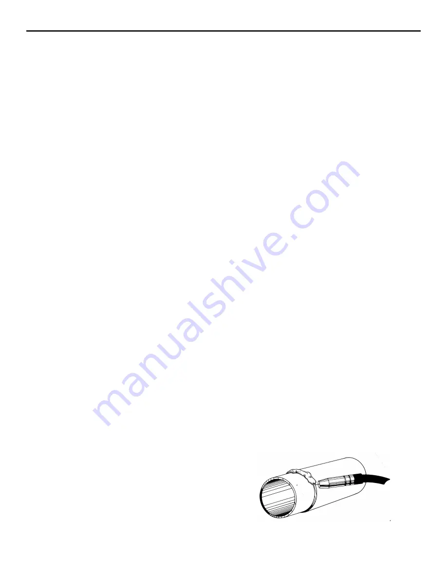
Welding Muffler Pipe

Muffler pipe welding is generally done with the conical 
nozzle installed on the welding gun.  The conical nozzle is 
used because the taper in the nozzle makes it easier to see the 
welding process and allows you to weld in tighter spots.

Prior to welding two pieces of muffler pipe together, it is 
recommended that two to three tack welds be placed around 
the pipe.  The tack welds will help hold the pipe in place while 
welding, and also prevent gaps caused by warpage.

Have 1/4" to 1/2" of welding wire protruding from the end 
of the gas nozzle.  Have the welding gun inclined at a 45-
degree angle to the pipe.  Aim the welding wire at the spot 
to be tacked and momentarily depress the trigger.  Hold 
the trigger long enough for the welding sound to smooth 
out (approximately one to two seconds).  Tack welding is 
generally done at the same power setting that normal pipe 
welding would be welded.

12

Muffler Pipe

Содержание MIG 2400

Страница 1: ...2400 Owner s Manual HTP America Inc 3200 Nordic Road Arlington Heights IL 60005 4729 1 800 USA WELD 847 357 0700 FAX 847 357 0744 www usaweld com Model 60240 24 America Inc...

Страница 2: ...in any event unless HTP America Inc receives notice of alleged breach of warranty within 30 days after the discovery actual or construction alleged breach of warranty specifying the claimed defect HT...

Страница 3: ...lose to degreasing or spraying operations Chlorinated hydrocarbon vapors may react with the ultra violet rays and form highly toxic phosgene gas If you develop momentary eye nose or throat irritation...

Страница 4: ...ed into the proper welding sound A hissing blowing sound with a ball of molten wire forming at the end of the wire and then dropping off indicates the wire feed rate is too slow A loud cracking noise...

Страница 5: ...s very similar to a lock on trigger on a drill or a grinder 7 Thermoswitch Indicator Light Your Mig 2400 has a duty cycle of 35 240 amps and 100 142 amps In the unlikely event you have welded long eno...

Страница 6: ...nd clamp be connected to a good clean surface Failure to do so will cause poor quality welds Place the ground clamp as close as possible to the area to be welded 14 Welding Gun Lead The welding gun le...

Страница 7: ...not enough pressure on the pressure roller Slowly tighten the pressure roller adjusting screw until the wire feeds evenly without slipping Then tighten an additional 1 4 turn for steel No additional t...

Страница 8: ...g beyond the weld and is not melting properly When tuned in properly a steady frying noise can be heard See Fig Z This means that the wire is melting properly and is melting right at the surface of th...

Страница 9: ...ll help to hold the panel in place while welding as well as to prevent panel separation caused by warpage Hold the welding gun at a 45 degree angle and use the edge of the gas nozzle to hold the two p...

Страница 10: ...Turn off the shield gas You are now ready to shrink Shrinking with your shrinking attachment is similar with any oxy acetylene torch the area is alternately heated and cooled until properly shrunk Th...

Страница 11: ...setting for hole filling is one to two settings below seam welding Welding Aluminum It is possible to weld aluminum with your MIG 2400 Depending on your application you may be able to get away with p...

Страница 12: ...d the metal and blow a big hole This is one of the problems of welding aluminum and just requires practice to overcome The end of the welding wire should always be clipped off with side cutters to aid...

Страница 13: ...posit a small puddle of molten wire on the stud and then allow it to cool Repeat the process until you have built up a small puddle of molten wire on the stud and allow it to cool Repeat the process u...

Страница 14: ...with spatter build up This nozzle is ruined because the operator allowed the spatter to build up excessively so the spatter has now welded itself to the inside of the gas nozzle Figures 11 and 12 sho...

Страница 15: ...330 Cylindrical Nozzle Aluminum Welding S4329 Spot Weld Nozzle Spot Welding 21 37F Small Conical Nozzle Tight Corners Changing the Drive Roll The drive roll has two grooves on it The narrower of the t...

Страница 16: ...e pressure roller has been adjusted too tightly When properly adjusted the drive roll will slip and bird nesting will never occur 16 Setting the Pressure on the Pressure Roller Prior to readjusting th...

Страница 17: ...welding gun Remove the liner positioner nut with a 12mm wrench and pull the old liner completely out of the welding gun See Fig 20 Remove the gas nozzle and contact tip If installing a Teflon liner i...

Страница 18: ...witch light will go out and the machine will be ready for use To keep the cooling system of your welder operating at peak performance it is necessary to remove the side panel and blow this area out wi...

Страница 19: ...a 1 8 40230 030 5356 Alloy Aluminum Wire 40230 4043 030 4043 Alloy Aluminum Wire Aluminum 16 ga 1 4 40235 035 5356 Alloy Aluminum Wire 40235 4043 035 4043 Alloy Aluminum Wire Stainless Steel 24 ga 1 8...

Страница 20: ...125 3 6 34 8 5 75 179 3 16 5 5 160 3 16 7 115 3 16 3 5 33 5 25 170 5 1 4 150 6 110 3 4 32 3 4 75 145 5 140 5 75 105 1 8 3 3 31 4 4 5 135 1 8 4 3 4 130 1 8 5 5 90 16 gauge 3 2 30 3 4 120 4 1 2 120 5 7...

Страница 21: ...21 HTP MIG 2400 Wiring Diagram...

Страница 22: ...22 Parts List MIG 2400...

Страница 23: ...2200 3 Fan 33 1 525014 0100 3 Fan Guard 34 1 706341 1701 1 Chain Illus Part Description 35 T1496004088 Wire Drive Brake Assy 37 3 2H0020 1789 0 Spacer 38 1 70C090 1010 1 Spindle Nut 40 1 506040 0330 3...

Страница 24: ...Nozzle Pkg 3 42 24108B Small Conical Nozzle Pkg 3 43 24106 Spot Weld Nozzle 50 24002 Swan Neck 56 15008 Handle Assy Blue Ergo does not include trigger Item Part Description 57 14009 Trigger 59 14018 S...

Страница 25: ...5 K61R Conductor Tube Retaining Nut 6 K81TWC Handle w Screws 7 K91 Trigger Switch w blades 8 K141 6 Cable Support Rubber 14 X040 Steel Liner 16 15041 Teflon Liner 16 19 K200 10E Power Cable 10 K200 1...

Отзывы: