HTP MIG 2400 Скачать руководство пользователя страница 10

Stitch  Welding

Your HTP MIG 2400 can perform a manual stitch weld.  
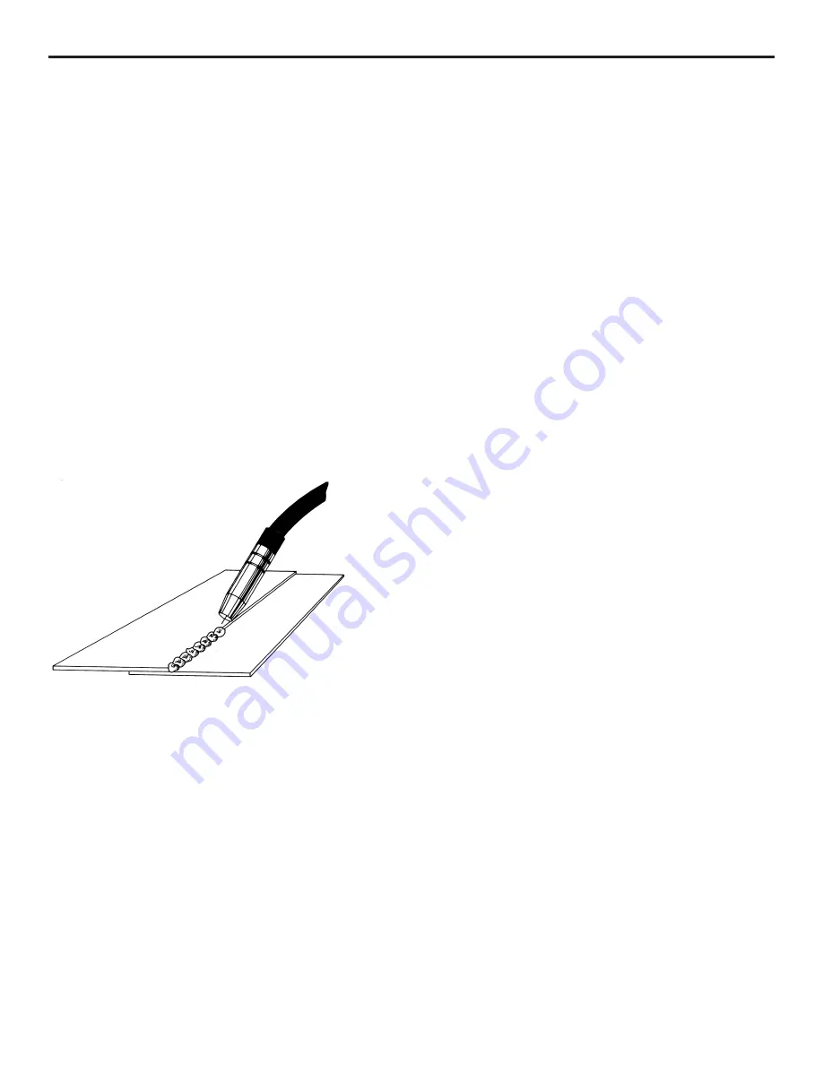
Stitch welding refers to a method of welding where you will 
weld, pause, weld, pause and continue in this cycle.  This 
method produces a welded seam which is actually a series 
of overlapping spot welds that give the appearance of "Fish 
Scales".  Stitch Welding is recommended for use on very 
thin materials, such as thin body panels or rusty exhaust pipe 
and in areas where is desired to keep warpage to a minimum.  
Stitch welding is also good for welders who have a problem 
keeping a steady hand, or maintaining a constant travel rate.

Stitch welding is performed with either the conical nozzle 
(#S4328) or the cylindrical nozzle (#S4330) and the decision 
is up to the operator.  For manual stitch welding, the trigger 
on the welding gun is depressed until 3/16" diameter puddle 
of metal is deposited on the workpiece.  Release the trigger 
and move the welding gun so that the center of the next puddle 
will lie on the edge of the first puddle.  Wait for the orange 
glow from the first puddle to disappear and deposit the second 
puddle of metal.  Continue this process until the seam is 
completed.

For a given thickness of metal, stitch welding is performed 
at the same or one power setting lower than seam welding.  
Stitch welding can be done on both steel and aluminum, and 
is recommended under 120 amps.  Stitch welding at higher 
power settings can result in serious burnback problems.

Metal Shrinking

Metal Shrinking is done with the optional shrinking 
attachment (Part #15003).  Remove the contact tip.  Release 
the pressure on the pressure roller and swing pressure roller 
out of the way.  Reel enough welding wire back onto the spool 
so that the shrinking attachment can be screwed into the swan 
neck.  Turn off the shield gas. You are now ready to shrink.

Shrinking with your shrinking attachment is similar with 
any oxy-acetylene torch; the area is alternately heated and 
cooled until properly shrunk.  The advantage to the shrinking 
attachment is that the heat is applied directly, the heat is much 
more concentrated, and there is less chance of fire because 
there are no open flames.

WARNING:  SHRINKING SHOULD ONLY BE DONE WITH 
THE COARSE POWER SWITCH IN POSITION 1 AND THE 
FINE POWER SWITCH IN POSITION 1

Spot Welding

Install the spot weld nozzle (Part #S4329) on the welding 
gun.  Using the Punch & Flange Tool (Part #12005 {5/16"} 
or #12003 {3/16"}) or the Heavy Duty Hole Punch (#12009) 
punch holes in the upper panel to be spotted on.  Feed some 
welding wire out past the end of the spot weld nozzle.  Using 
sidecutters, clip the welding wire off flush with the end of 
the spot weld prongs.  This will aid you in centering the gas 
nozzle over the punched hole.

Use a relatively high power setting, probably a minimum of 
3 on the coarse setting, but it all depends on the thickness of 
sheet metal you are working with.

Turn the power selector to position 3 on the coarse setting 
and setting 3, 4, 5 or 6 on the fine setting (3 or 4 for thin 
sheet metal, 6 for heavier sheet metal).  Tune in the wire 
feed rate until the proper frying noise is heard.  Reduce the 
wire feed rate just until the machine begins to sound out of 
tune.  A slightly slower wire feed rate will produce flatter 
spot welds, however, do not reduce the wire feed rate when 
performing overhead spot welds.  Turn the spot weld timer 
on to approximately 2.  Place the welding gun so that the 
welding wire is centered over the punched hole (see fig. 7).  
Depress the trigger on the welding gun.  Your welder will 
stop automatically.  Examine the spot weld.  If the hole is not 
completely full, either the welding wire was not centered over 
the hole or there was not enough spot weld time.  The spot 

10

Figure 6  
“Stitch Welding”

Содержание MIG 2400

Страница 1: ...2400 Owner s Manual HTP America Inc 3200 Nordic Road Arlington Heights IL 60005 4729 1 800 USA WELD 847 357 0700 FAX 847 357 0744 www usaweld com Model 60240 24 America Inc...

Страница 2: ...in any event unless HTP America Inc receives notice of alleged breach of warranty within 30 days after the discovery actual or construction alleged breach of warranty specifying the claimed defect HT...

Страница 3: ...lose to degreasing or spraying operations Chlorinated hydrocarbon vapors may react with the ultra violet rays and form highly toxic phosgene gas If you develop momentary eye nose or throat irritation...

Страница 4: ...ed into the proper welding sound A hissing blowing sound with a ball of molten wire forming at the end of the wire and then dropping off indicates the wire feed rate is too slow A loud cracking noise...

Страница 5: ...s very similar to a lock on trigger on a drill or a grinder 7 Thermoswitch Indicator Light Your Mig 2400 has a duty cycle of 35 240 amps and 100 142 amps In the unlikely event you have welded long eno...

Страница 6: ...nd clamp be connected to a good clean surface Failure to do so will cause poor quality welds Place the ground clamp as close as possible to the area to be welded 14 Welding Gun Lead The welding gun le...

Страница 7: ...not enough pressure on the pressure roller Slowly tighten the pressure roller adjusting screw until the wire feeds evenly without slipping Then tighten an additional 1 4 turn for steel No additional t...

Страница 8: ...g beyond the weld and is not melting properly When tuned in properly a steady frying noise can be heard See Fig Z This means that the wire is melting properly and is melting right at the surface of th...

Страница 9: ...ll help to hold the panel in place while welding as well as to prevent panel separation caused by warpage Hold the welding gun at a 45 degree angle and use the edge of the gas nozzle to hold the two p...

Страница 10: ...Turn off the shield gas You are now ready to shrink Shrinking with your shrinking attachment is similar with any oxy acetylene torch the area is alternately heated and cooled until properly shrunk Th...

Страница 11: ...setting for hole filling is one to two settings below seam welding Welding Aluminum It is possible to weld aluminum with your MIG 2400 Depending on your application you may be able to get away with p...

Страница 12: ...d the metal and blow a big hole This is one of the problems of welding aluminum and just requires practice to overcome The end of the welding wire should always be clipped off with side cutters to aid...

Страница 13: ...posit a small puddle of molten wire on the stud and then allow it to cool Repeat the process until you have built up a small puddle of molten wire on the stud and allow it to cool Repeat the process u...

Страница 14: ...with spatter build up This nozzle is ruined because the operator allowed the spatter to build up excessively so the spatter has now welded itself to the inside of the gas nozzle Figures 11 and 12 sho...

Страница 15: ...330 Cylindrical Nozzle Aluminum Welding S4329 Spot Weld Nozzle Spot Welding 21 37F Small Conical Nozzle Tight Corners Changing the Drive Roll The drive roll has two grooves on it The narrower of the t...

Страница 16: ...e pressure roller has been adjusted too tightly When properly adjusted the drive roll will slip and bird nesting will never occur 16 Setting the Pressure on the Pressure Roller Prior to readjusting th...

Страница 17: ...welding gun Remove the liner positioner nut with a 12mm wrench and pull the old liner completely out of the welding gun See Fig 20 Remove the gas nozzle and contact tip If installing a Teflon liner i...

Страница 18: ...witch light will go out and the machine will be ready for use To keep the cooling system of your welder operating at peak performance it is necessary to remove the side panel and blow this area out wi...

Страница 19: ...a 1 8 40230 030 5356 Alloy Aluminum Wire 40230 4043 030 4043 Alloy Aluminum Wire Aluminum 16 ga 1 4 40235 035 5356 Alloy Aluminum Wire 40235 4043 035 4043 Alloy Aluminum Wire Stainless Steel 24 ga 1 8...

Страница 20: ...125 3 6 34 8 5 75 179 3 16 5 5 160 3 16 7 115 3 16 3 5 33 5 25 170 5 1 4 150 6 110 3 4 32 3 4 75 145 5 140 5 75 105 1 8 3 3 31 4 4 5 135 1 8 4 3 4 130 1 8 5 5 90 16 gauge 3 2 30 3 4 120 4 1 2 120 5 7...

Страница 21: ...21 HTP MIG 2400 Wiring Diagram...

Страница 22: ...22 Parts List MIG 2400...

Страница 23: ...2200 3 Fan 33 1 525014 0100 3 Fan Guard 34 1 706341 1701 1 Chain Illus Part Description 35 T1496004088 Wire Drive Brake Assy 37 3 2H0020 1789 0 Spacer 38 1 70C090 1010 1 Spindle Nut 40 1 506040 0330 3...

Страница 24: ...Nozzle Pkg 3 42 24108B Small Conical Nozzle Pkg 3 43 24106 Spot Weld Nozzle 50 24002 Swan Neck 56 15008 Handle Assy Blue Ergo does not include trigger Item Part Description 57 14009 Trigger 59 14018 S...

Страница 25: ...5 K61R Conductor Tube Retaining Nut 6 K81TWC Handle w Screws 7 K91 Trigger Switch w blades 8 K141 6 Cable Support Rubber 14 X040 Steel Liner 16 15041 Teflon Liner 16 19 K200 10E Power Cable 10 K200 1...

Отзывы: