Now that the pipe is tacked into place, you are ready to weld
the pipe. Once again, have 1/4" to 1/2" of welding wire
protruding from the gas nozzle. Again, the welding gun is
generally held at a 45-degree angle to the pipe. It also may
be tilted at a 45-angle to the left or right. Rest the gas nozzle
on the pipe and have the wire pointing at the spot where
the welding is to begin. Press the trigger to begin welding.
Slowly move the welding gun along the weld at a constant
rate. A jerky, inconsistent, or too rapid rate will cause arc
instability and a sputtering welding sound. A rate that is too
slow will cause burn-through. It is also important that you
position the welding gun so that you can see the welding wire
as it comes out past the gas nozzle. The light produced from
the wire coming in contact with the work is the only thing that
will allow you to see the "seam" through the welding helmet.
If the gas nozzle is blocking your view of the wire, then there
will not be sufficient light to see the welding process.
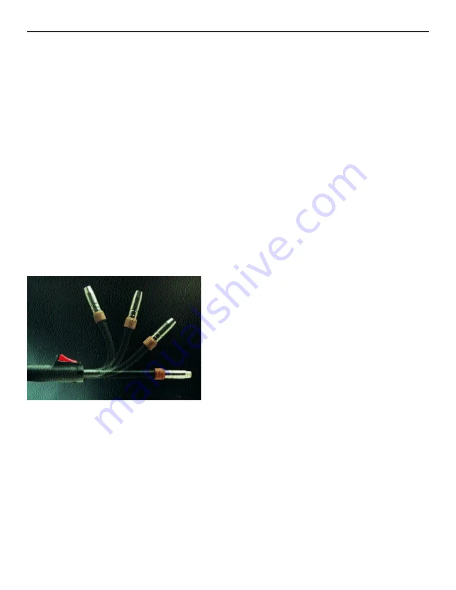
HTP has a flexible swan neck welding gun available (Part
#13510) available for welding muffler pipe. The flexible swan
neck makes it possible to bend the swan neck to get into hard
to reach places and to get up over the top of the muffler pipe.
13
Flex Neck
Broken Stud Removal
Your HTP MIG Welder can be used to remove exhaust
manifold studs which have broken off flush or are protruding
slightly from the exhaust manifold. In many instances, it is
not even necessary to remove the exhaust manifold from the
car.
Start with the power set at 4,1 or 3,6. This will ensure good
adhesion of the molten wire to the stud. Point your wire
directly at the stud and momentarily depress the trigger. Weld
long enough to deposit a small puddle of molten wire on the
stud and then allow it to cool. Repeat the process until you
have built up a small puddle of molten wire on the stud and
allow it to cool. Repeat the process until you have built up
a small amount of weld. Reduce the power to 3,2 or 2,6 and
continue building the weld until 1/4" to 1/2" is protruding
from the exhaust manifold. The lower power setting will allow
you to build up the weld faster. Now take a 5/8" or 3/4" nut
and place it on the stud. Weld the nut to the stud.
Allow the stud to cool completely. Heat the exhaust manifold
as you normally would and remove the stud. Shops have
proven this process works 80% of the time.
Welding Cast Iron
Your HTP MIG Welder has the ability to weld cast iron using
75% Argon – 25% CO2 shielding gas and cast iron welding
wire (Part #50235). The cast iron welding wire will also allow
you to weld mild steel to cast iron.
When welding with the cast iron wire, welding techniques are
the same as the welding techniques for mild steel. Due to the
.035" diameter, wire feed rates for cast iron welding wire will
be lower for a give power setting than the .030" diameter steel
wire. However, the machine is tuned in the same way as with
the steel wire, listening for the "sizzling" noise.
Depending on the thickness of the material, it may be desirable
to preheat the casting to ensure adequate penetration. When
welding a crack, it may be beneficial to "vee" out the crack.
In order to reduce the possibility of further propagation; drill
small holes at both ends of the crack. It is also a good idea
to make short welds to reduce the possibility of overheating
the cast iron around the weld area. Then immediately after
welding, lightly tap (peen) the weld with a ball-peen hammer
to stress relieve the weld area.
The more time spent in surface preparation of cast iron welds
(cleaning the surface, veeing out cracks, etc.) the better the
results and the stronger the weld will be.
Содержание MIG 2400
Страница 21: ...21 HTP MIG 2400 Wiring Diagram...
Страница 22: ...22 Parts List MIG 2400...


