72
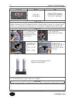
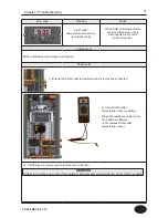
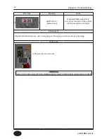
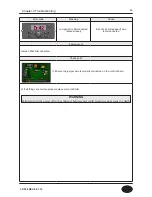
Error code
Meaning
Cause
Ignition failure
(manual reset)
During ignition trials, if unit failed
to ignite 10 times continuously,
error code 11 will appear.
Failure event
If the unit failed to detect flame during ignition sequence pre-purge time will exceed 10 sec, and error code
Er 11 will appear.
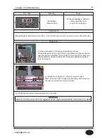
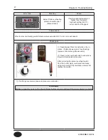
Check point
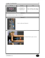
① Check separation distance
after removing the flame rod.
(separation distance: 1/8”)
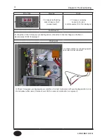
② Check ignition
transformer and
electrical wires for
proper connection.
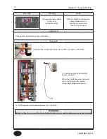
④ Please check
flame detector sensor’s
connecting line and
ensure correct position
as shown.
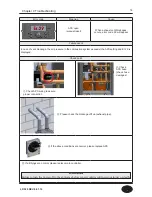
③ Check Gas Inlet
Pressure Range:
NG:
3.5” WC ~ 14” WC
LP:
3.5” WC ~ 14”WC
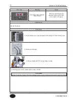
⑤ If the flame sensing viewing port is excessively discolored, loss of fame will occur. To correct this
problem, replace the flame viewing glass.
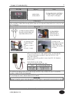
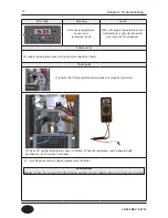
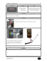
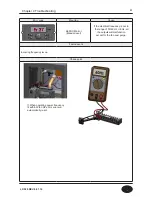
■ From more than DC 2.5V after ignition safety, cut-off will appear
① When setting before ignition is less than DC 2.5V: Re
-
place flame sensor.
② When setting after ignition is more than DC 2.5V: Replace
flame sensor.
⑥ If all things are normal, please replace main controller.
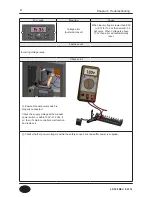
Flame detector sensor setting
(Please check after closing front cover)
ITEM
Normal operating settings
Before ignition
More than DC 2.5V
After ignition
Less than DC 2.5V
Chapter 4 Troubleshooting
WARNING
Failure to turn the power off to the appliance before repair could result in serious injury or death.
1/8”
LP-528 REV. 8.01.14
Содержание EFTC-140F
Страница 3: ...1 LP 528 REV 8 01 14 ...
Страница 11: ...9 Domestic Hot Water Mode Space Heating Mode Flow chart Chapter 1 Product Characteristics LP 528 REV 8 01 14 ...
Страница 13: ...11 Operation flow chart Chapter 1 Product Characteristics LP 528 REV 8 01 14 ...
Страница 14: ...12 Operation flow chart Chapter 1 Product Characteristics LP 528 REV 8 01 14 ...
Страница 15: ...13 Wiring Diagram Chapter 1 Product Characteristics LP 528 REV 8 01 14 ...
Страница 16: ...14 Wiring Diagram Chapter 1 Product Characteristics Mixing Valve LP 528 REV 8 01 14 ...
Страница 41: ...39 Installer Setting Mode Control panel mode Chapter 3 How to use control panel LP 528 REV 8 01 14 ...
Страница 42: ...40 Chapter 3 How to use control panel LP 528 REV 8 01 14 ...
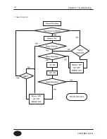
Страница 67: ...65 Chapter 4 Troubleshooting 1 Flame Detection LP 528 REV 8 01 14 ...
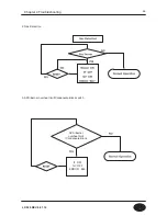
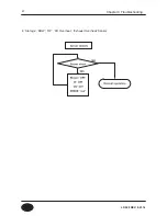
Страница 69: ...67 4 Storage DHW OP CH Overheat Exhaust Overheat Sensor Chapter 4 Troubleshooting LP 528 REV 8 01 14 ...
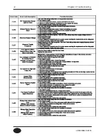
Страница 70: ...68 Error code Chapter 4 Troubleshooting LP 528 REV 8 01 14 ...
Страница 71: ...69 Chapter 4 Troubleshooting LP 528 REV 8 01 14 ...
Страница 72: ...70 Chapter 4 Troubleshooting LP 528 REV 8 01 14 ...
Страница 106: ...104 1 Cabinet Replacement Parts Chapter 7 Repair Part Diagram LP 528 REV 8 01 14 ...
Страница 107: ...105 Chapter 7 Repair Part Diagram LP 528 REV 8 01 14 ...
Страница 108: ...106 2 Combustion System Replacement Parts Chapter 6 Repair Parts Diagram LP 528 REV 8 01 14 ...
Страница 109: ...107 Chapter 7 Repair Part Diagram LP 528 REV 8 01 14 ...
Страница 110: ...108 Memo LP 528 REV 8 01 14 ...
Страница 111: ...109 Memo LP 528 REV 8 01 14 ...
Страница 112: ...110 Memo LP 528 REV 8 01 14 ...


