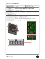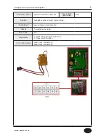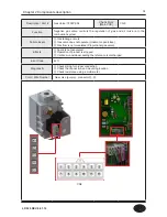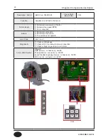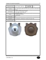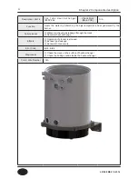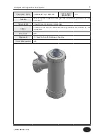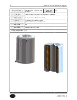
18
Description / Part #
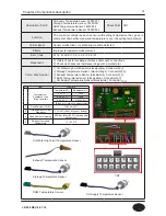
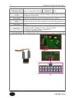
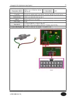
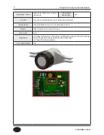
CH Supply Temperature Sensor: 7855P-031
Storage Temperature Sensor: 7855P-057
DHW Temperature Sensor: 7855P-094
Exhaust Temperature Sensor: 7855P-092
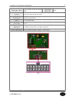
Check Point CN7
Function
The controller compares each sensor with setting temperature then goes to
safety shut down when measured temperature is over the setting temperature.
Failure Event
Sensor malfunction or overheating condition detected.
Effects
Improper temperature measurement.
Error Code
Er 16, Er 28, Er 30, Er 32, Er 33, Er 35
Diagonostic
①
Visibly check for breakage of wires and/or each connections
②
Check each sensor’s resistance range with a multi-meter.
Color / Wire Number
①
CH Water High Limit Sensor (black/purple): Connector
⑭
,
⑦
②
Storage Temperature Sensor (black/orange): Connector
⑬
,
⑥
③
Exhaust Temperature Sensor (black/white): Connector
⑫
,
⑤
④
DHW Temperature Sensor (black/yellow): Connector
⑩
,
③
⑤
CH Supply Temperature Sensor (black/white): Connector
⑨
,
②
NO
Item
Standard
1
Temperature –
Resistance Type
Idling Condition
Temperature(
℃
)
Resistance(k
Ω
)
0 ± 0.1
℃
-10.99
25 ± 0.1
℃
-3.906
85 ± 0.1
℃
0.552 ± 3%
( )Blank is for reference measurement
2
Fixed Number (25/85)
3482.4K ± 2%
3
Fixed Number of Heat
Dissipation
2.5mW/
℃
(Min.) (While not boiling)
4
Fixed Number of Heating 8(15)Sec (Max)(63.2% reaching time
while boiling)
5
Range of Workable
Temperature
- 4 ~ 230 º
F
① ② ③ ④ ⑤ ⑥ ⑦
⑧ ⑨ ⑩ ⑪ ⑫ ⑬ ⑭
CH Water High Limit Temperature Sensor
Exhaust Temperature Sensor
Storage Temperature Sensor
DHW Temperature Sensor
CH Supply Temperature Sensor
CN7
Chapter 2 Components description
LP-528 REV. 8.01.14
Содержание EFTC-140F
Страница 3: ...1 LP 528 REV 8 01 14 ...
Страница 11: ...9 Domestic Hot Water Mode Space Heating Mode Flow chart Chapter 1 Product Characteristics LP 528 REV 8 01 14 ...
Страница 13: ...11 Operation flow chart Chapter 1 Product Characteristics LP 528 REV 8 01 14 ...
Страница 14: ...12 Operation flow chart Chapter 1 Product Characteristics LP 528 REV 8 01 14 ...
Страница 15: ...13 Wiring Diagram Chapter 1 Product Characteristics LP 528 REV 8 01 14 ...
Страница 16: ...14 Wiring Diagram Chapter 1 Product Characteristics Mixing Valve LP 528 REV 8 01 14 ...
Страница 41: ...39 Installer Setting Mode Control panel mode Chapter 3 How to use control panel LP 528 REV 8 01 14 ...
Страница 42: ...40 Chapter 3 How to use control panel LP 528 REV 8 01 14 ...
Страница 67: ...65 Chapter 4 Troubleshooting 1 Flame Detection LP 528 REV 8 01 14 ...
Страница 69: ...67 4 Storage DHW OP CH Overheat Exhaust Overheat Sensor Chapter 4 Troubleshooting LP 528 REV 8 01 14 ...
Страница 70: ...68 Error code Chapter 4 Troubleshooting LP 528 REV 8 01 14 ...
Страница 71: ...69 Chapter 4 Troubleshooting LP 528 REV 8 01 14 ...
Страница 72: ...70 Chapter 4 Troubleshooting LP 528 REV 8 01 14 ...
Страница 106: ...104 1 Cabinet Replacement Parts Chapter 7 Repair Part Diagram LP 528 REV 8 01 14 ...
Страница 107: ...105 Chapter 7 Repair Part Diagram LP 528 REV 8 01 14 ...
Страница 108: ...106 2 Combustion System Replacement Parts Chapter 6 Repair Parts Diagram LP 528 REV 8 01 14 ...
Страница 109: ...107 Chapter 7 Repair Part Diagram LP 528 REV 8 01 14 ...
Страница 110: ...108 Memo LP 528 REV 8 01 14 ...
Страница 111: ...109 Memo LP 528 REV 8 01 14 ...
Страница 112: ...110 Memo LP 528 REV 8 01 14 ...


