99
Main components Replacement Instructions
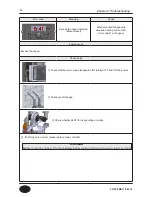
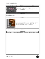
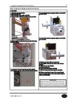
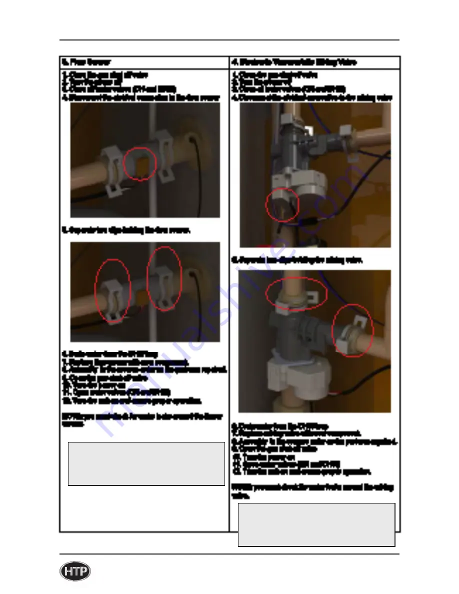
3. Flow Sensor
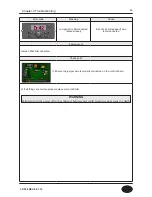
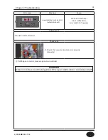
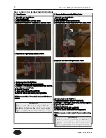
4. Mixing Valve
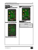
1. Switch main gas valve to close’s.
2. Switch manual power switch to 120V OFF.
3. Switch water valve to close.
4. Separate sensor connected to flow sensor.
5. Separate two clips fixing the flow sensor.
6. Replace flow sensor with new component.
7. Assemble flow sensor and cold water inlet pipe and fix
flow sensor with two clips.
8. Attach temperature sensor on the flow sensor.
9. Switch water valve to open.
10. Switch manual power switch to open.
11. Switch main gas valve to open.
12. Test whether it operate normally.
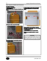
1. Switch main gas valve to close’s
2. Switch manual power switch to 120V OFF.
3. Switch water valve to close.
4. Separate wire connector connected to mixing valve.
5. Separate two clips fixing the mixing valve.
6. Replace mixing valve with new component.
7. Assemble flow sensor and pipe and fix mixing valve
with two clips.
8. Connect wire connector on the mixing valve.
9. Switch water valve to open.
10. Switch manual power switch to open.
11. Switch main gas valve to open.
12. Test whether it operate normally.
Chapter 5 Replacement Instructions
LP-528 REV. 8.01.14
WARNING
Failure to turn the power and gas off to the
appliance and ensure the unit is cool before
repair could result in serious injury or death.
WARNING
Failure to turn the power and gas off to the
appliance and ensure the unit is cool before
repair could result in serious injury or death.
Содержание EFTC-140F
Страница 3: ...1 LP 528 REV 8 01 14 ...
Страница 11: ...9 Domestic Hot Water Mode Space Heating Mode Flow chart Chapter 1 Product Characteristics LP 528 REV 8 01 14 ...
Страница 13: ...11 Operation flow chart Chapter 1 Product Characteristics LP 528 REV 8 01 14 ...
Страница 14: ...12 Operation flow chart Chapter 1 Product Characteristics LP 528 REV 8 01 14 ...
Страница 15: ...13 Wiring Diagram Chapter 1 Product Characteristics LP 528 REV 8 01 14 ...
Страница 16: ...14 Wiring Diagram Chapter 1 Product Characteristics Mixing Valve LP 528 REV 8 01 14 ...
Страница 41: ...39 Installer Setting Mode Control panel mode Chapter 3 How to use control panel LP 528 REV 8 01 14 ...
Страница 42: ...40 Chapter 3 How to use control panel LP 528 REV 8 01 14 ...
Страница 67: ...65 Chapter 4 Troubleshooting 1 Flame Detection LP 528 REV 8 01 14 ...
Страница 69: ...67 4 Storage DHW OP CH Overheat Exhaust Overheat Sensor Chapter 4 Troubleshooting LP 528 REV 8 01 14 ...
Страница 70: ...68 Error code Chapter 4 Troubleshooting LP 528 REV 8 01 14 ...
Страница 71: ...69 Chapter 4 Troubleshooting LP 528 REV 8 01 14 ...
Страница 72: ...70 Chapter 4 Troubleshooting LP 528 REV 8 01 14 ...
Страница 106: ...104 1 Cabinet Replacement Parts Chapter 7 Repair Part Diagram LP 528 REV 8 01 14 ...
Страница 107: ...105 Chapter 7 Repair Part Diagram LP 528 REV 8 01 14 ...
Страница 108: ...106 2 Combustion System Replacement Parts Chapter 6 Repair Parts Diagram LP 528 REV 8 01 14 ...
Страница 109: ...107 Chapter 7 Repair Part Diagram LP 528 REV 8 01 14 ...
Страница 110: ...108 Memo LP 528 REV 8 01 14 ...
Страница 111: ...109 Memo LP 528 REV 8 01 14 ...
Страница 112: ...110 Memo LP 528 REV 8 01 14 ...

