36
[Initial power-up condition]
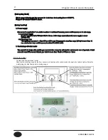
When power is supplied, zero point of the mixing valve is checked for 6 seconds. After that, normal 800 steps
function is in progress. At this time, if zero point is not confirmed, Er 66 occurs. After error is automatically re
stored when zero point was confirmed, normal 800step function is in progress.
[Central Heating mode]
Setting the central heating target temperature can be done through the front display panel. The setpoint
temperature is memorized even if power is lost. The T/T signal from a room thermostat will activate the
central heating mode. DHW mode is always the priority. The central heating mode will shut off until DHW
demand is satisfied.
[DHW mode]
DHW mode is activated by the flow sensor sensing flow of 0.5 GPM or above. When there is DHW demand,
flow sensor monitor the frequency (range: 8Hz to12Hz), with 2 minutes. The storage tank will maintain a user
defined setpoint. DHW temperature can be set 95~140℉(35℃~60℃). If there is DHW demand, burner starts
and mixing valve operates automatically.
[Freeze protection mode]
Freeze protection mode operates with 2 stages as shown below:
1. Stage 1:
CH supply and/or storage tank water temperature sensors detect temperature below 46℉(8℃), first stage of this
mode is activated. With the first stage, while burner does not turn ON, internal DHW and CH circulation pumps operate
for 600 seconds and stops for 30 seconds repeatedly until the temperature is reached to 50℉(10℃).
2. Stage2:
After stage 1 operation, if CH supply and DHW storage tank temperatures are below 41℉(5℃), second stage of
this mode is operational and the burner is activated. With the second stage, both CH and DHW storage tank circu
lation pumps are run until CH supply and/or DHW storage tank temperature reaches 104℉(40℃). If the unit is
powered off, the internal circulation pumps operate, but the burner remains off.
Error code Er.85 is displayed when the temperature is below 34℉(1℃), and will automatically reset when temperature
above 50℉(10℃).
[Water level sensor Mode]
This mode senses water amount inside of boiler and prevent shortage of water. It senses water level real time and
if shortage is detected more than 4 sec, combustion stops. If water level is reached desired amount for more than
4 sec, boiler starts operating, also to supply with enough water, inner recirculation pump operates after 30sec,
heating circulation pump operates 30 sec runs, 10sec stops.
[Mixing valve operation]
During a DHW demand, mixing valve modultaes to control the DHW outlet temperature by mixing the cold and hot
water.
When there is no DHW demand, mixing valve stands vy at 800 steps. To prevent the mixing valve mechanism from
getting stuck, it moves 2,000 steps (fully closed) for 5 sec, then moves to default position (fully opened) and finally b
ack to 800 step.
[Storage Mode]
Storage mode is used to keep the internal indiret storage tank heated to a user defined setting. This mode is very
important to prevent any delay of domestic hot water demand.
Chapter 3 How to use control panel
■ Function explanation
LP-528 REV. 8.01.14
Содержание EFTC-140F
Страница 3: ...1 LP 528 REV 8 01 14 ...
Страница 11: ...9 Domestic Hot Water Mode Space Heating Mode Flow chart Chapter 1 Product Characteristics LP 528 REV 8 01 14 ...
Страница 13: ...11 Operation flow chart Chapter 1 Product Characteristics LP 528 REV 8 01 14 ...
Страница 14: ...12 Operation flow chart Chapter 1 Product Characteristics LP 528 REV 8 01 14 ...
Страница 15: ...13 Wiring Diagram Chapter 1 Product Characteristics LP 528 REV 8 01 14 ...
Страница 16: ...14 Wiring Diagram Chapter 1 Product Characteristics Mixing Valve LP 528 REV 8 01 14 ...
Страница 41: ...39 Installer Setting Mode Control panel mode Chapter 3 How to use control panel LP 528 REV 8 01 14 ...
Страница 42: ...40 Chapter 3 How to use control panel LP 528 REV 8 01 14 ...
Страница 67: ...65 Chapter 4 Troubleshooting 1 Flame Detection LP 528 REV 8 01 14 ...
Страница 69: ...67 4 Storage DHW OP CH Overheat Exhaust Overheat Sensor Chapter 4 Troubleshooting LP 528 REV 8 01 14 ...
Страница 70: ...68 Error code Chapter 4 Troubleshooting LP 528 REV 8 01 14 ...
Страница 71: ...69 Chapter 4 Troubleshooting LP 528 REV 8 01 14 ...
Страница 72: ...70 Chapter 4 Troubleshooting LP 528 REV 8 01 14 ...
Страница 106: ...104 1 Cabinet Replacement Parts Chapter 7 Repair Part Diagram LP 528 REV 8 01 14 ...
Страница 107: ...105 Chapter 7 Repair Part Diagram LP 528 REV 8 01 14 ...
Страница 108: ...106 2 Combustion System Replacement Parts Chapter 6 Repair Parts Diagram LP 528 REV 8 01 14 ...
Страница 109: ...107 Chapter 7 Repair Part Diagram LP 528 REV 8 01 14 ...
Страница 110: ...108 Memo LP 528 REV 8 01 14 ...
Страница 111: ...109 Memo LP 528 REV 8 01 14 ...
Страница 112: ...110 Memo LP 528 REV 8 01 14 ...

