background image


PVCHECK 

33


In general:  

The rated v

alues of Voc and Isc are the values found in the instrument’s internal modules’ DB (see 

§ 5.6).  


  The overall value of the results:   


o

  OK: if all results under STC are OK,  

o

  NO if one of the results under STC is NO  

23. Press the 

 key to go back to the previous screen.  

24. Press  the 

SAVE


key  to  store  the  test  result  in  the  instrument’s  memory  (see  §  7.2)  or  the 

ESC/MENU

 key to exit the screen without saving and go back to the main measuring screen.  


CAUTION


The  average  values  of 

Voc  and  Isc  are  displayed  in  the  results’  page.  These  values 

include the average values of Voc and Isc under OPC conditions calculated as mean of 
the last 10 tests previously saved. If the user has carried out and saved a number of tests 
<10 or reset the average values (see § 6.3.4) the average value displayed during test 
N+1 will be calculated on the available N values. 


6.3.4.  Reset Averages  

If  irradiance  values  are  measured,  the  instrument  provides  a  result  by  comparing  the  values 

measured with the average values calculated according to the previously saved measured.  

In this case, the average values calculated by the instrument are therefore particularly important. In 

case  a  new  measurement  campaign  is  started  with  significant  variations  in  irradiance  or 
temperature,  it  is  advisable  to  set  the  average  reference  values  to  zero  in  order  to  make  new 
calculations  based  on  new  measurements.  To  reset  the  average  values,  please  keep  to  the 
following steps:  


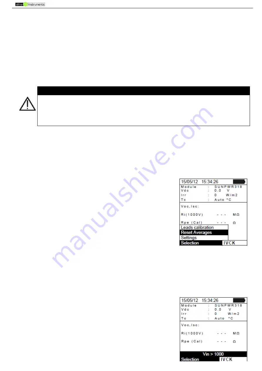
1. In IVCK mode, press the 

ENTER


key, select “

Reset Averages

” 

and confirm by pressing 

ENTER

 again to zero the average values 

calculated until that moment.  


The average values are automatically reset also 

modifying and then saving

 one of the following 

parameters:  


  Type of PV module  

  Number of modules per string  


The average values are not reset if the operator changes operating mode and then goes back to 

this mode.  


6.3.4.1.  Anomalous situations when performing IVCK tests  

1.  In  case  the  instrument  detects  a  voltage  higher  than  1000V  at 

terminals P-N, P-E and N-E, it does not carry out the test, gives 
out a long sound and displays the message “Vin > 1000”.  

Содержание PVCHECK

Страница 1: ...Manual PVCHECK EAN 8033772797467...

Страница 2: ...PVCHECK 2 PVCHECK...

Страница 3: ...te unit Pyranometer 10 5 1 5 Irradiance 11 5 1 6 DC Clamp 11 5 2 EFF EFFICIENCY TEST SETTINGS FOR PV INSTALLATIONS 12 5 2 1 Instrument settings 12 5 2 2 System parameters 13 5 2 3 Selection of the com...

Страница 4: ...VING IVCK M AND LOW MEASURED RESULTS 44 7 3 OPERATIONS WITH RESULTS 45 7 3 1 Recalling on the display the PV efficiency results 45 7 3 2 Recalling on the display the results of IVCK M and LOW measurem...

Страница 5: ...xists In this manual and on the instrument the following symbols are used CAUTION observe the instructions given in this manual an improper use could damage the instrument or its components High volta...

Страница 6: ...easured circuits reads Circuits are divided into the following measurement categories Measurement category IV is for measurements performed at the source of the low voltage installation Examples are e...

Страница 7: ...power at PV modules strings outputs Measurement of irradiation W m2 by means of a reference cell connected to the optional remote unit SOLAR 02 Measurement of module and environmental temperature by...

Страница 8: ...of the internal batteries When battery charge decreases to a minimum level the symbol appears on the display In this case stop testing and replace the batteries according to the indications given in 9...

Страница 9: ...of the front part of the instrument CAPTION 1 Input for irradiation measuring probe 2 Input for auxiliary temperature measuring probe DC current clamp IVCK EFF 3 P N inputs for DC voltage IVCK EFF Ins...

Страница 10: ...y is a graphic module with a resolution of 128 x 128 dots The display s first line indicates the system s date time and contains the battery charge indicator At the bottom of the display the function...

Страница 11: ...e different settings of the instrument Settings will be maintained also after switching off the instrument 5 1 1 General 1 Position the cursor onto General by using the arrow keys and confirm with ENT...

Страница 12: ...row keys 4 Press the SAVE key to save the settings made the message Data saved will be displayed for a few seconds Press the ESC MENU key to exit without saving and go back to the previous screen 5 1...

Страница 13: ...the message Data saved will be displayed for a few seconds Press the ESC MENU key to exit without saving and go back to the previous screen CAUTION The 0 W m2 setting for parameter Irr min IVCK allows...

Страница 14: ...erator 2 Press the ENTER key The instrument shows the following options System parameters and Instrument settings 3 Use the arrow keys to select Instrument settings and confirm with ENTER The instrume...

Страница 15: ...nstallation expressed in kW Range coefficient of power variation with temperature characteristic parameter of PV modules range 1 00 0 01 C NOCT rated operating temperature of the cell characteristic p...

Страница 16: ...ended to select T Env correction Corr Type Temperature used Tcel Calculation of nDC Ref where Symbol Description Measuring unit Gp Irradiance measured on PV module surface W m2 GSTC Standard Irradianc...

Страница 17: ...rrow keys to select Settings and confirm with ENTER The instrument shows the following screen 4 Using the arrow keys it is possible to set the maximum limit value of Rpe resistance which the instrumen...

Страница 18: ...tings saved for test voltage also affect the settings for the insulation measurement contained in the IVCK measurement MENU IVCK 5 5 IVCK SETTINGS FOR IVCK QUICK TEST The purpose of this measurement i...

Страница 19: ...nstrument Allowable values 0 25 The value between brackets 4 indicates the reading error of the instrument in Voc measurement Tol Isc percentage value of the desired limit tolerance set by the operato...

Страница 20: ...5 9 99A 0 01A Isc Impp Toll Negative tolerance for Pmax provided by the module manufacturer 0 25 0 0 1 100 Tol Pnom 25 0 99W 1 Toll Positive tolerance for Pmax provided by the module manufacturer 0 25...

Страница 21: ...ss the SAVE key to save the name of the new module thus defined or the ESC MENU key to exit without saving 6 Insert the value of each parameter see Table 1 according to the possible datasheet of the M...

Страница 22: ...arrow keys Keep the arrow keys pressed to carry out a quick setting of the values If the value of any parameter is unknown press and hold the HELP key for a few seconds to set the default values 7 Pr...

Страница 23: ...safety while making the connections disable the system being measured by means of the switches breakers upstream and downstream of the DC AC converter inverter Fig 4 Connection of instrument for effic...

Страница 24: ...itive output conductor of the string respecting the direction of the arrow found on the clamp itself as indicated in 10 Fig 4 Connection of instrument for efficiency measurement on a PV installation 1...

Страница 25: ...icate that the unit has detected the data with solar irradiation minimum threshold set see 5 1 5 22 With the message READY shown on the display wait for approximately 1 minute in order to take a certa...

Страница 26: ...1 Select the option NO as regards the type of remote unit to be used during EFF test see 5 1 4 set the full scale of the DC clamp see 5 2 1 a possible correction factor of the DC clamp see 0 the integ...

Страница 27: ...he instrument s display 9 At any time it will be possible to analyze the current recording status by pressing the MENU key The following information will be shown Starting date and time of recording T...

Страница 28: ...mode is suitable to carry out a test session on a considerable number of strings as quickly as possible 0 recommended 700W m2 the instrument carries out all tests provided for I V test manages all co...

Страница 29: ...n real time Tc value of module temperature see 5 5 1 Voc Isc section with display of result OK NO of Voc and Isc measurement Ri the value in brackets may be NO selected test voltage see 5 5 1 The valu...

Страница 30: ...the time necessary to obtain a steady value 12 The value of insulation resistance is shown in field Ri and the message OK appears in case the result of the test is positive measured value higher than...

Страница 31: ...Switch on the instrument by pressing the ON OFF key 2 Irradiance measurement is carried out in one of the following modes Measurement by reference cell directly connected to PVCHECK Measurement by ref...

Страница 32: ...nclinometer M304 11 Connect the output of the cell corresponding to the type of module being tested to the IRR input of the instrument using the cable supplied with the cell or to the PYRA CELL input...

Страница 33: ...tial screen of IVCK mode the following values are displayed in real time Module type of module being tested Vdc value of output voltage from module string Irr irradiance from a direct measurement or S...

Страница 34: ...itive measured value higher than the minimum limit value set on the instrument 19 With continuity measurement selected the instrument goes on by opening the short circuit and carrying out the test bet...

Страница 35: ...esult by comparing the values measured with the average values calculated according to the previously saved measured In this case the average values calculated by the instrument are therefore particul...

Страница 36: ...s according to the prescriptions IEC EN62446 guideline In general the instrument measures insulation in the following modes FIELD mode used for measuring insulation resistance of a PV field photovolta...

Страница 37: ...ative pole of the PV field and the earthing Rp final value of the measurement obtained by the parallel of Ri e Ri values which is compared with the Ri min limit by the instrument key access to the sec...

Страница 38: ...screen to the side 2 Press the ENTER key activate Settings and possibly change the desired parameters see 5 4 The following parameters are shown on the display Ins Test selected test voltage 250 500...

Страница 39: ...reen 6 4 4 Measuring insulation STRING mode CAUTION The maximum current which can be measured by the instrument is 10A Before carrying out the measures of Insulation in STRING mode always ensure that...

Страница 40: ...rement is complete the instrument provides the Ri value i e the minimum value of insulation resistance of the PV module string or of other objects being tested continuously measured during the whole d...

Страница 41: ...t the test and displays the message Low voltage 6 5 MEASUREMENT OF CONTINUITY ON PV MODULES STRINGS FIELDS LOW 6 5 1 Foreword The purpose of this measurement is to test the continuity of protective co...

Страница 42: ...e value of compensated resistance carry out a new compensation procedure with a resistance higher than 5 such as for example with open leads The value in Rcal is zeroed on the display 6 5 3 Measuring...

Страница 43: ...instrument displays the message Measuring as shown in the screen to the side 6 At the end of measurement the instrument provides the value of resistance of the object being tested If the result is lo...

Страница 44: ...4 contact service Internal instrument error Database full The number of modules added to the internal DB is 30 Module already added The name of the module has already been added to the DB Memory full...

Страница 45: ...contact service Internal instrument error FRAM error contact service Internal instrument error RTC Error contact service Internal instrument error RADIO error contact service Internal instrument error...

Страница 46: ...or the system 2 For each of the 3 markers Plant String and Module it is possible to assign custom labels except if already permanently assigned to another marker the message Label already assigned is...

Страница 47: ...he datum has been saved in the instrument DESCRIPTION indicates the description provided by the user when saving the datum 4 Select the type of SMP datum the item Open and confirm with ENTER The instr...

Страница 48: ...Numeric display 1 Select a line corresponding to a saved result and press ENTER 2 Select Open and press ENTER to open the section where measurement results are displayed as Numeric screens of measure...

Страница 49: ...voltage The Rp final value of the measurement obtained by the parallel of Ri e Ri values which is compared with the Ri min limit by the instrument 7 For LOW test there are the values of the following...

Страница 50: ...SC MENU key to open the main menu 4 Use the arrow keys to select PC to access data transfer mode and confirm with ENTER 5 The instrument shows the following screen 6 The instrument shows the following...

Страница 51: ...f 10 TECHNICAL SPECIFICATIONS 10 1 TECHNICAL SPECIFICATIONS FOR PV INSTALLATION EFFICIENCY Accuracy is indicated as reading no of digits resolution at 23 C 5 C 80 HR DC voltage Range V Resolution V Ac...

Страница 52: ...0 1 1 0 rdg 1 C 10 3 TECHNICAL SPECIFICATIONS FOR ELECTRICAL SAFETY Continuity of protective conductors LOW Range Resolution Accuracy 0 00 1 99 0 01 2 0 rdg 2dgt 2 0 19 9 0 1 20 199 1 Test current 20...

Страница 53: ...ution level 2 Measurement category CAT III 300V to earth Max 1000V between inputs P N E C 10 5 GENERAL CHARACTERISTICS Display and memory Type of display LCD custom 128x128 pxl with backlighting Saved...

Страница 54: ...er see 5 2 3 Corr Tcel value Mathematical relationship for nDC calculation Standard Result Tmod Tcel Measured module temp value Italian guideline CEI 82 25 OK NO Tenv Tcel Calculated module temp value...

Страница 55: ...the following cases Repair and or replacement of accessories and battery not covered by warranty Repairs that may become necessary as a consequence of an incorrect use of the instrument or due to its...

Страница 56: ...v 181002 2018 10 02 11 20...

Отзывы: