


Theory of Operation
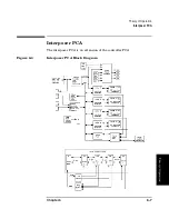
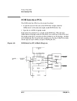
SCSI Interface PCA
Chapter 6
6-14
The two large components on the PCA are the Field-Programmable Gate
Array and the microprocessor. The microprocessor is an 80C52 that has
flash-programmable memory on board. (There are no boot ROMs on this
PCA).
After the jukebox runs it selftest on wakeup, in instructs the PCA to
come up in whichever mode has been selected by the user. It can come up
either as a repeater or in LUN mode. Communication from the robotic
controller is through the GPIO bus cable. (If the GPIO cable is not
connected at startup, the PCA will come up as a repeater.)
A “heartbeat” LED is located on the bottom edge of the board. This LED
will continuously flash at a slow rate when power is applied. If the LED
is either on steady or off, this indicates a problem with the PCA.
An LED, visible through the top of the interface enclosure, is mounted
between the interface connectors on each side. These LEDs light to show
which interface has been selected. If the wrong interface type is
connected to the interface connector on this PCA, the LED will
continuously and rapidly flash to alert the user to this error. No damage
is caused to the chips on the PCA by having connectors in the wrong
position.
During powerup, the position of the interface selector switch is checked
to see which external bus is active and if the proper bus type is on the
selected interface port.
If the differential bus is active, the DIFFSENSE signal on the SCSI bus
is checked. If this signal is LOW, it means that a single-ended bus has
erroneously been connected to the differential connector. The bus is
immediately made inactive to protect the chips.
In addition to checking the position of the interface select switch on
powerup, the controller is informed of any change to this switch during
normal operation. If the switch position is changed, a BUS RESET signal
is sent to the robotics controller on the internal SCSI bus
NOTE
It is important to provide proper termination on whichever external
SCSI bus (single-ended or differential) that is in use. If the SCSI bus is
not being daisy-chained to another peripheral (and terminated there)
then termination must be provided at this PCA.
Содержание Surestore 160ex - Optical Jukebox
Страница 10: ...TOC x Contents ...
Страница 14: ...Tables TOC xiv ...
Страница 15: ...Chapter 1 1 1 Product Information 1 Product Information ...
Страница 26: ...Product Information Environmental Specifications Chapter 1 1 12 ...
Страница 27: ...Chapter 2 2 1 Installation 2 Installation ...
Страница 30: ...Installation Identifying Controls and Features Chapter 2 2 4 Figure 2 2 Left Side ...
Страница 47: ...Chapter 3 3 1 Operation and Configuration 3 Operation and Configuration ...
Страница 50: ...Operation and Configuration Operating the Control Panel Chapter 3 3 4 Figure 3 1 The Jukebox Control Panel ...
Страница 52: ...Operation and Configuration Operating the Control Panel Chapter 3 3 6 Figure 3 2 Jukebox Display Menu Tree ...
Страница 60: ...Operation and Configuration Changing the Administration Menu Password Chapter 3 3 14 flash ROM ...
Страница 75: ...Chapter 4 4 1 Troubleshooting and Diagnostics 4 Troubleshooting and Diagnostics ...
Страница 122: ...Troubleshooting and Diagnostics Running an Internal Test Chapter 4 4 48 ...
Страница 123: ...Chapter 5 5 1 Removal and Replacement 5 Removal and Replacement ...
Страница 129: ...Removal and Replacement Service Access Chapter 5 5 7 Removal and Replacement Front Panel ...
Страница 136: ...Removal and Replacement Replacing the Control Panel Assembly Chapter 5 5 14 oriented incorrectly ...
Страница 188: ...Removal and Replacement Replaceable Parts Chapter 5 5 66 Figure 5 43 Exploded View 1 of 3 ...
Страница 189: ...Removal and Replacement Replaceable Parts Chapter 5 5 67 Removal and Replacement Figure 5 44 Exploded View 2 of 3 ...
Страница 190: ...Removal and Replacement Replaceable Parts Chapter 5 5 68 Figure 5 45 Exploded View 3 of 3 ...
Страница 191: ...Removal and Replacement Replaceable Parts Chapter 5 5 69 Removal and Replacement Figure 5 46 Power Cabling ...
Страница 192: ...Removal and Replacement Replaceable Parts Chapter 5 5 70 Figure 5 47 Rope and Pulley System ...
Страница 193: ...Chapter 6 6 1 Theory of Operation 6 Theory of Operation ...
Страница 218: ...Theory of Operation Optical Drive Mechanism Chapter 6 6 26 ...
Страница 219: ...Appendix A A 1 Safety and Regulatory A Safety and Regulatory Information ...