Theory of Operation
Interposer PCA
Chapter 6
6-8
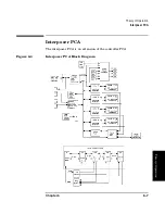
(Use the top portion of the diagram for the following explanation.)
The single, GPIO and power connection from the controller PCA is J20.
Address decode and data buffering takes addresses from the controller
PCA and sends the data to proper locations and takes received data and
routes the data to the proper destination.
Ground, 5 V, and 12V are supplied to the optical drives directly through
their own power circuitry on the interposer PCA (see the top of the
diagram). The controller can control power application to the drives
through this circuitry. In the event of a drive failure, the controller sets
the displays of the online drive repair LEDs.
Power to the drives can also be removed by unplugging the J19, J18, J8,
and J6 connectors. These connectors are the four-pin connectors on the
drive power cables and act like power on/off switches. Power to the drives
is supplied through the eight-pin connectors J26, J25, J16, and J15.
The controller communicates to the drives through each drive’s “AC
interface connector.” Status signals and commands available include:
requesting a drive eject, spin-down requests, drive sensing, error status
detection, sensing presence of a cartridge, resetting the drive, sensing a
loaded cartridge, setting write with verify, and setting the SCSI ID for
the drive.
The controller can talk (serial protocol) to each drive individually
through the serial port multiplexer (MUX). This communication path,
which is also routed through the “AC interface connector,” enables the
controller to request the drive’s serial number and revision of firmware
being used. The controller can also use the serial MUX to directly talk to
the configuration module.
The vertical-clear-path emitter drivers on the interposer PCA output to
the emitters in the vertical-path-clear LEDs through connector J4.
J3 receives mailslot information and front panel key strokes. The
controller can read key strokes through the J3 connection, but the
controller sends front panel display information directly to J2.
(Use the bottom portion of the diagram for the following explanation.)
J1 is the SCSI input from the host computer. The input is directly bused
to connectors J24, J23, J14, and J13, which are the connections to drives
1, 2, 3, and 4 respectively.The bus uses 48 of the 50 pins of the SCSI bus.
SCSI is
totally separate
from any other electronics on the interposer PCA
except for two signals, Req and Ack.The Ack signal comes from the host
Содержание Surestore 160ex - Optical Jukebox
Страница 10: ...TOC x Contents ...
Страница 14: ...Tables TOC xiv ...
Страница 15: ...Chapter 1 1 1 Product Information 1 Product Information ...
Страница 26: ...Product Information Environmental Specifications Chapter 1 1 12 ...
Страница 27: ...Chapter 2 2 1 Installation 2 Installation ...
Страница 30: ...Installation Identifying Controls and Features Chapter 2 2 4 Figure 2 2 Left Side ...
Страница 47: ...Chapter 3 3 1 Operation and Configuration 3 Operation and Configuration ...
Страница 50: ...Operation and Configuration Operating the Control Panel Chapter 3 3 4 Figure 3 1 The Jukebox Control Panel ...
Страница 52: ...Operation and Configuration Operating the Control Panel Chapter 3 3 6 Figure 3 2 Jukebox Display Menu Tree ...
Страница 60: ...Operation and Configuration Changing the Administration Menu Password Chapter 3 3 14 flash ROM ...
Страница 75: ...Chapter 4 4 1 Troubleshooting and Diagnostics 4 Troubleshooting and Diagnostics ...
Страница 122: ...Troubleshooting and Diagnostics Running an Internal Test Chapter 4 4 48 ...
Страница 123: ...Chapter 5 5 1 Removal and Replacement 5 Removal and Replacement ...
Страница 129: ...Removal and Replacement Service Access Chapter 5 5 7 Removal and Replacement Front Panel ...
Страница 136: ...Removal and Replacement Replacing the Control Panel Assembly Chapter 5 5 14 oriented incorrectly ...
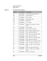
Страница 188: ...Removal and Replacement Replaceable Parts Chapter 5 5 66 Figure 5 43 Exploded View 1 of 3 ...
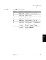
Страница 189: ...Removal and Replacement Replaceable Parts Chapter 5 5 67 Removal and Replacement Figure 5 44 Exploded View 2 of 3 ...
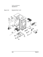
Страница 190: ...Removal and Replacement Replaceable Parts Chapter 5 5 68 Figure 5 45 Exploded View 3 of 3 ...
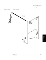
Страница 191: ...Removal and Replacement Replaceable Parts Chapter 5 5 69 Removal and Replacement Figure 5 46 Power Cabling ...
Страница 192: ...Removal and Replacement Replaceable Parts Chapter 5 5 70 Figure 5 47 Rope and Pulley System ...
Страница 193: ...Chapter 6 6 1 Theory of Operation 6 Theory of Operation ...
Страница 218: ...Theory of Operation Optical Drive Mechanism Chapter 6 6 26 ...
Страница 219: ...Appendix A A 1 Safety and Regulatory A Safety and Regulatory Information ...

