


Theory of Operation
SCSI Interface PCA
Chapter 6
6-13
T
h
eory
o
f Operat
io
n
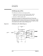
Figure 6-6
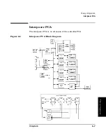
SCSI Interface PCA
The jukebox communicates to the PCA through a GPIO bus.
The differential and single-ended connectors are on the top of the PCA
and the single-ended bus connection to the jukebox is on the bottom. A
slider switch between the two external connectors selects which type of
input will be accepted.
Four jumpers select the configuration for termination alternatives
—
J6 - enable/disable differential host TERMPOWER. PIN 1 and 2
jumpered together allows the PCA to provide TERMPOWER to
the differential external [host] SCSI bus (default).
— J5 - enable/disable internal bus TERMPOWER. PINS 1 and 2
jumpered together allows the PCA to provide TERMPOWER to
the internal SCSI bus (default).
— J4 - bus terminator configuration. PIN 1 and 2 jumpered together
enable bus termination (default). When enabled, active
termination is supplied for the internal bus at this PCA;
termination at the other end of the SCSI cable is by a clamp
terminator attached to the SCSI cable near the last drive
connection.
— J1 - enable/disable single-ended host TERMPOWER. PIN 1 and 2
jumpered together allows the PCA to provide TERMPOWER to
the single-ended external [host] bus (default).
Содержание Surestore 160ex - Optical Jukebox
Страница 10: ...TOC x Contents ...
Страница 14: ...Tables TOC xiv ...
Страница 15: ...Chapter 1 1 1 Product Information 1 Product Information ...
Страница 26: ...Product Information Environmental Specifications Chapter 1 1 12 ...
Страница 27: ...Chapter 2 2 1 Installation 2 Installation ...
Страница 30: ...Installation Identifying Controls and Features Chapter 2 2 4 Figure 2 2 Left Side ...
Страница 47: ...Chapter 3 3 1 Operation and Configuration 3 Operation and Configuration ...
Страница 50: ...Operation and Configuration Operating the Control Panel Chapter 3 3 4 Figure 3 1 The Jukebox Control Panel ...
Страница 52: ...Operation and Configuration Operating the Control Panel Chapter 3 3 6 Figure 3 2 Jukebox Display Menu Tree ...
Страница 60: ...Operation and Configuration Changing the Administration Menu Password Chapter 3 3 14 flash ROM ...
Страница 75: ...Chapter 4 4 1 Troubleshooting and Diagnostics 4 Troubleshooting and Diagnostics ...
Страница 122: ...Troubleshooting and Diagnostics Running an Internal Test Chapter 4 4 48 ...
Страница 123: ...Chapter 5 5 1 Removal and Replacement 5 Removal and Replacement ...
Страница 129: ...Removal and Replacement Service Access Chapter 5 5 7 Removal and Replacement Front Panel ...
Страница 136: ...Removal and Replacement Replacing the Control Panel Assembly Chapter 5 5 14 oriented incorrectly ...
Страница 188: ...Removal and Replacement Replaceable Parts Chapter 5 5 66 Figure 5 43 Exploded View 1 of 3 ...
Страница 189: ...Removal and Replacement Replaceable Parts Chapter 5 5 67 Removal and Replacement Figure 5 44 Exploded View 2 of 3 ...
Страница 190: ...Removal and Replacement Replaceable Parts Chapter 5 5 68 Figure 5 45 Exploded View 3 of 3 ...
Страница 191: ...Removal and Replacement Replaceable Parts Chapter 5 5 69 Removal and Replacement Figure 5 46 Power Cabling ...
Страница 192: ...Removal and Replacement Replaceable Parts Chapter 5 5 70 Figure 5 47 Rope and Pulley System ...
Страница 193: ...Chapter 6 6 1 Theory of Operation 6 Theory of Operation ...
Страница 218: ...Theory of Operation Optical Drive Mechanism Chapter 6 6 26 ...
Страница 219: ...Appendix A A 1 Safety and Regulatory A Safety and Regulatory Information ...