


Removal and replacement procedures 68
8.
Select
Reboot the System
to exit the utility and resume the boot process.
The IP address of the enabled dedicated iLO connector appears on the POST screen on the subsequent
boot-up. Access the Network Options screen again to view this IP address for later reference.
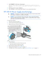
Front I/O assemblies for LFF and SFF chassis using
thumbscrew rack ears
CAUTION:
To prevent damage to electrical components, take the appropriate anti-static
precautions before beginning any installation, removal, or replacement procedure. Improper
grounding can cause electrostatic discharge.
To remove the component:
1.
Power down the server (on page
27
).
2.
Remove all power:
a.
Disconnect each power cord from the power source.
b.
Disconnect each power cord from the server.
3.
Do one of the following:
o
Extend the server from the rack (on page
28
).
o
Remove the server from the rack (on page
30
).
4.
If installed, remove the security bezel ("
Remove the security bezel (optional)
" on page
27
).
5.
Remove the access panel ("
Access panel
" on page
37
).
6.
Release the front I/O cabling from the server:
a.
Detach the ambient thermal sensor cable from its clip.
b.
Release the ambient thermal sensor cable from the front chassis cable clip.
c.
Disconnect the front I/O assembly cable.
—
Front I/O cabling disconnection in an LFF chassis
Содержание ProLiant DL180 Gen9
Страница 13: ...Customer self repair 13 ...
Страница 14: ...Customer self repair 14 ...
Страница 15: ...Customer self repair 15 ...
Страница 18: ...Illustrated parts catalog 18 ...
Страница 23: ...Illustrated parts catalog 23 ...
Страница 117: ...Cabling 117 Item Description 5 Fan 5 cable GPU power drive cabling FlexibleLOM sideband signal cabling ...
Страница 121: ...Cabling 121 Item Description 3 USB 3 0 connector cable ...


