background image

Illustrated Parts Catalog 

1-6


HP ProLiant DL145 Generation 2 Server Maintenance and Service Guide 

HP Contact Information 

For the name of the nearest HP authorized reseller:  


In the United States, see the HP US service locator webpage 
(http://www.hp.com/service_locator). 


In other locations, see the Contact HP worldwide (in English) webpage 
(

http://welcome.hp.com/country/us/en/wwcontact.html

). 

For HP technical support: 


In the United States, for contact options see the Contact HP United States webpage 
(

http://welcome.hp.com/country/us/en/contact_us.html

). To contact HP by phone: 


Call 1-800-HP-INVENT (1-800-474-6836). This service is available 24 hours a day, 
7 days a week. For continuous quality improvement, calls may be recorded or monitored.  


If you have purchased a Care Pack (service upgrade), call 1-800-633-3600. For more 
information about Care Packs, refer to the HP website (

http://www.hp.com

). 


In other locations, see the Contact HP worldwide (in English) webpage 
(

http://welcome.hp.com/country/us/en/wwcontact.html

). 

Before You Contact HP  

Be sure to have the following information available before you call HP: 


Technical support registration number (if applicable) 


Product serial number 


Product model name and number 


Applicable error messages 


Add-on boards or hardware 


Third-party hardware or software 


Operating system type and revision level 

All manuals and user guides at all-guides.com

Содержание ProLiant DL145

Страница 1: ...HP ProLiant DL145 Generation 2 Server Maintenance and Service Guide June 2006 Third Edition Part Number 381741 003 All manuals and user guides at all guides com a l l g u i d e s c o m ...

Страница 2: ...emark of The Open Group Linux is a U S registered trademark of Linus Torvalds OpenServer is a U S registered trademark of The SCO Group Torx is a trademark of Camcar Textron Screw Mfg Co Other products or system names appearing in this document are trademarks or registered trademarks of their respective owners Further the or TM symbols are not used in the text HP ProLiant DL145 Generation 2 Server...

Страница 3: ...ols on Equipment 2 2 Rack Warnings 2 3 Server Warnings and Precautions 2 4 Hardware Configuration Information 2 4 Electrostatic Discharge Information 2 4 Pre installation Procedures 2 5 Post installation Procedures 2 6 Powering Down the Server 2 6 Opening the Server 2 7 Drive Bay Configuration 2 8 Cable Routing Diagrams 2 9 Optical Media Drive 2 11 Hard Drives 2 13 System Board Configuration 2 27 ...

Страница 4: ...onents 4 2 Rear Panel Components 4 3 System Board Components 4 4 Front Panel Board Components 4 7 Status LED Indicators 4 10 Front Panel LED Indicators 4 10 Rear Panel LED Indicators 4 12 System Board LED Indicators 4 13 Chapter 5 Physical and Operating Specifications System Unit 5 2 Memory 5 5 Processor 5 5 IDE CD ROM Drive 5 6 Non hot plug Hard Drives 5 7 SCSI Hard Drive 5 7 SATA Hard Drive 5 8 ...

Страница 5: ... required to address a system problem The specialist will also determine whether you can replace the part Replacement parts are express shipped Most in stock parts are shipped the very same day you contact HP You may be required to send the defective part back to HP unless otherwise instructed Available for most HP products currently under warranty or contract For information on the warranty servi...

Страница 6: ...rs in the EU only The use of the Original Spare part is regulated by RoHS legislation If your unit contains a part that is labeled with the Modified Spare number the Modified Spare must be ordered as the replacement part in the EU If your unit contains a part that is labeled with the Original Spare number please order the Original Spare as the replacement part in the EU In this case either the Ori...

Страница 7: ...or heat sink 389311 001 408296 001 Yes 3 Processor Yes Single core processors a AMD Opteron Processor 246 2 0 GHz 390283 001 b AMD Opteron Processor 248 2 2 GHz 390284 001 c AMD Opteron Processor 252 2 6 GHz 382043 005 d AMD Opteron Processor 254 2 8 GHz Dual core processors a AMD Opteron Processor 265 1 8 GHz 395811 005 b AMD Opteron Processor 270 2 0 GHz 395812 005 c AMD Opteron Processor 275 2 ...

Страница 8: ...42 001 Yes 8 64 bit 133 MHz low profile SCSI controller board 389324 001 Yes 9 64 bit 133 MHz PCI X riser board assembly a Standard height PCI X riser board b Low profile PCI X riser board 389313 001 408292 001 408293 001 Yes 10 PCI Express riser board 391845 001 408294 001 Yes Mass storage devices 11 Optical media drive a IDE CD ROM drive 24X b DVD ROM drive 8X 390535 001 383981 005 Yes 12 Non ho...

Страница 9: ... Network Interface Card NIC options 26 10 1000BCM VD PCI X board 268794 001 Yes 27 PCI Gigabit switch adapter 366603 001 Yes 28 10 100 1000 T PCI NIC board 353446 001 Yes 29 PCI Express Gigabit NIC board 366605 001 Yes 30 PCI X Gigabit DP UTP board 313586 001 Yes 31 PCI Express dual port 4x IB adapter board 374931 001 Yes 32 PCI Express dual port 4x IB controller board 374932 001 Yes REQUIREMENT F...

Страница 10: ...VENT 1 800 474 6836 This service is available 24 hours a day 7 days a week For continuous quality improvement calls may be recorded or monitored If you have purchased a Care Pack service upgrade call 1 800 633 3600 For more information about Care Packs refer to the HP website http www hp com In other locations see the Contact HP worldwide in English webpage http welcome hp com country us en wwcont...

Страница 11: ...rly Hardware Configuration Tools In performing any hardware configuration procedure you may need the following tools T 15 Torx screwdriver Flat blade screwdriver The following references and software tools may also be used HP ProLiant DL145 Generation 2 Server Support CD IPMI Event Log Diagnostics software NOTE The figures used in this chapter to illustrate procedural steps are labeled numerically...

Страница 12: ...zard The potential for injury exists if warnings are not observed Consult your documentation for specific details This symbol indicates the presence of hazardous energy circuits or electric shock hazards Refer all servicing to qualified personnel WARNING To reduce the risk of injury from electric shock hazards do not open this enclosure Refer all maintenance upgrades and servicing to qualified per...

Страница 13: ...gestellt werden da das Gehäuse eine glänzende Front aufweist WARNING To reduce the risk of personal injury or damage to equipment always ensure that the rack is adequately stabilized before extending a component outside the rack A rack may become unstable if more than one component is extended for any reason Extend only one component at a time WARNING To reduce the risk of personal injury or damag...

Страница 14: ...ith a regulating uninterruptible power supply UPS This device protects the hardware from damage caused by power surges and voltage spikes and keeps the system in operation during a power failure CAUTION The server must always be operated with the system top cover closed Proper cooling is not achieved if the system top cover is removed Hardware Configuration Information Electrostatic Discharge Info...

Страница 15: ...alling removing components may cause serious damage as well as bodily harm 1 Turn off the server and all the peripherals connected to it Refer to the Powering Down the Server section on the next page for detailed instructions on how to completely power down the server 2 Disconnect the AC power cord from the power supply cable socket located on the server rear panel to eliminate the risk of electri...

Страница 16: ...n the Server The server does not completely power down when the power button is pressed The button toggles between On and Standby The standby position removes power from most electronics and the drives but some internal circuitry remains active To completely remove all power from the system disconnect all power cords from the server To power down the server 1 Shut down server as directed by the OS...

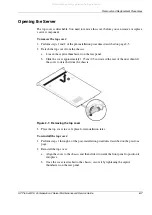
Страница 17: ...nel b Slide the cover approximately 1 25 cm 0 5 in toward the rear of the unit then lift the cover to detach it from the chassis Figure 2 1 Removing the top cover 3 Place the top cover in a safe place for reinstallation later To reinstall the top cover 1 Perform steps 1 through 4 of the post installation procedures described on the previous page 2 Reinstall the top cover a Align the cover to the c...

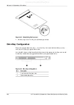
Страница 18: ...orts three drive bays two drive bays for 1 inch hard disk drives and one drive bay for a slim type optical media drive Go to the HP website at http www hp com and refer to the options list for this server model for the latest information on supported hard drives and optical media drives Figure 2 3 Drive bay configuration Item Description 1 1 inch hard disk drive bays two 2 Optical media device bay...

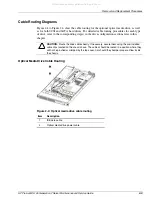
Страница 19: ...ing step s in the drive configuration sections later in this chapter CAUTION Route the drive cables neatly If necessary secure them using the pre installed cable clips located on the chassis base The cables should be routed in a position where they will not be pinched or crimped by the top cover nor should they hamper proper airflow inside the chassis Optical Media Drive Cable Routing Figure 2 4 O...

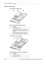
Страница 20: ...drive power cables 2 SCSI drive data cable when the controller card is installed in the standard height full length PCI X riser board slot 3 SCSI drive data cable when the controller card is installed in the low profile PCI X riser board slot SATA Hard Drive Cable Routing Figure 2 6 SATA hard drive cable routing when No Description 1 SATA drive power cable 2 SATA drive data cable All manuals and u...

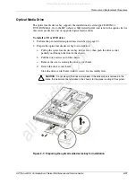
Страница 21: ...al media device bay for installation a Pull up the optical media device bay release lever then push the drive carrier partially out through the front of the chassis b Pull the drive carrier out of the chassis c Remove the screw securing the drive carrier bezel d Detach the drive carrier bezel Store the drive carrier bezel with its screw for reassembly later CAUTION Do not discard the drive carrier...

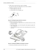
Страница 22: ... Installing the optical media drive in its carrier 5 Install the new optical drive into the chassis a Slide the CD ROM drive assembly into the chassis until the media device bay release lever snaps into place b Route the optical drive s power cables through the cable management opening of the chassis partition wall c Connect the IDE data and power cables to their corresponding connectors on the re...

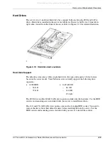
Страница 23: ...th a single hard drive the type and capacity of which varies based on the server model Your ProLiant server currently supports the following drive capacities SCSI HDD 36 GB 72 GB SATA HDD 80 GB 160 GB 250 GB The SCSI drive and the 80 GB SATA drive options include only the hard disk Use the HDD carriers and mounting screws included with your server to install these drives The 160 and 250 GB SATA dr...

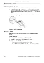
Страница 24: ...y Install hard disks in the drive carriers included with the server chassis using four of the six HDD mounting screws pre installed in each of the two HDD carriers Figure 2 11 HDD mounting screws Removing a Hard Drive Instructions on how to remove a currently installed hard drive are described in the next section To remove a hard drive 1 Perform the pre installation procedures described on page 2 ...

Страница 25: ...crews that secure the hard drive to the carrier b Remove the hard drive from its carrier Figure 2 13 Removing the hard drive from its carrier IMPORTANT If you removed a hard drive without plans of installing a new one you must reinstall the mounting screws at their pre installed location for future use then reinstall the HDD carrier in the chassis for the proper cooling of the system All manuals a...

Страница 26: ...pied remove the currently installed drive following the procedures described on page 2 14 If the desired drive bay is empty perform step 3 of the To remove a hard drive section on page 2 15 then remove four mounting screws from the HDD carrier You will use these screws to install the new drive 3 Install the new SCSI hard drive in its carrier If you are installing the new drive in a previously occu...

Страница 27: ...e standard height full length 64 bit 133 MHz PCI X riser board slot 1 Remove the PCI riser board assembly following the procedures described on page 2 37 2 Identify the slot that is compatible with the SCSI controller board you intend to install 3 Pull out the slot cover from the selected slot Store it for reassembly later CAUTION Do not discard the slot cover If the expansion board is removed in ...

Страница 28: ... by replacing the default bracket attached to the board with a different sized one The different sized bracket and instructions on how to attach it to the board is included in the option kit 5 Verify that the board s default bracket is compatible with the configuration of the selected slot If it is not compatible replace the bracket with one that is compatible 6 Slide the SCSI controller board int...

Страница 29: ...tion for instructions on how to route the SCSI drive cables To route the SCSI drive cables Cable routing for SCSI hard drive varies depending on which expansion slot you installed the SCSI controller board in the low profile slot or in the standard height full length slot and to a certain extent to the location of the cable connectors on the SCSI controller board you installed Figure 2 21 SCSI cab...

Страница 30: ...ing connector on the SCSI controller board b Fold the connector end of the SCSI cable in the manner illustrated in the following figure then route the cable towards the air duct The marked side of the cable should be facing down Figure 2 22 SCSI cable routing for low profile controller boards phase 1 c Use the two retainer tabs on the air duct to secure the cable d Open the protective mylar sheet ...

Страница 31: ...for low profile controller boards phase 3 i Route the power cable through the cable management opening of the chassis partition wall j Connect the SCSI and power cables to their corresponding connectors on the rear of the new drive Make sure the terminated end of the SCSI cable is positioned in the manner illustrated in Figure 2 25 k Check that all cables are clear of the hard drive carrier and ar...

Страница 32: ...I controller board for detailed procedures To route the SCSI drive cables when the controller board is installed in the standard height full length expansion slot 1 Connect the SCSI cable to the SCSI controller board a Connect the cable to the corresponding connector on the SCSI controller board b Fold the connector end of the SCSI cable in the manner illustrated in the following figure c Attach a...

Страница 33: ...ll connection to the system board b Tighten the two captive thumbscrews to secure the assembly to the chassis c Route the SCSI cable between the IDE data cable and the power supply unit making sure it lays flat between this space Figure 2 27 SCSI cable routing for standard height full length controller boards phase 2 d Disconnect the following cables from their system board connectors the 8 pin AT...

Страница 34: ...able routing for standard height full length controller boards phase 3 g Route the SCSI and power cables through the cable management opening of the chassis partition wall h Connect the SCSI and power cables to their corresponding connectors on the rear of the new drive Make sure the terminated end of the SCSI cable is positioned in the manner illustrated Figure 2 29 i Check that all cables are cl...

Страница 35: ...scribed on page 2 6 4 Set up the SCSI configuration Refer to the documentation that came with the SCSI controller board for detailed procedures Configuring a SATA Hard Drive Configuring a SATA hard drive is a two step process that includes 1 Install the SATA hard drive 2 Set up the SATA configuration For detailed procedures refer to the Server Support CD or to the operating system documentation Al...

Страница 36: ...Connect the SATA and power cables to their corresponding connectors on the rear of the new drive c Check that all cables are clear of the hard drive carrier and are properly routed to their corresponding connectors then tighten the screw that secures the hard drive assembly to the chassis Figure 2 30 Routing the SATA drive cables 3 Perform the post installation procedures described on page 2 6 4 S...

Страница 37: ...or sockets U11 and U22 is shown in Figure 2 31 Figure 2 31 AMD Opteron processor sockets Guidelines for Installing a Processor When installing a processor in the server observe the following important guidelines Processor socket 1 U22 must always be populated If no processor is installed in this socket the system will fail to boot and halt during POST This error prevents the system from functionin...

Страница 38: ...ure to flash the ROM before installing processors can cause system failure To prevent the heat sink from tilting to one side during installation removal procedures observe a diagonally opposite pattern an X pattern when loosening and tightening the four spring loaded screws To remove a processor 1 Perform the pre installation procedures described on page 2 5 2 If necessary remove any accessory boa...

Страница 39: ...ly to release the heat sink from the processor base b Lift the heat sink away from the system board Figure 2 34 Removing the heat sink 6 Remove the processor a Disengage the socket retention lever from the processor base b Grasp the processor by its edges and lift it out of its socket Figure 2 35 Removing the processor 7 Place the processor on a static dissipating work surface or inside an anti st...

Страница 40: ...ot discard the processor air baffle If the processor in processor socket 1 is removed in the future the air baffle must be reinstalled to maintain proper cooling 4 Disengage the socket retention lever from the processor base 5 Install the processor a Hold the processor by its edges and align it over the empty processor socket Make sure that pin 1 of the processor indicated by the gold triangle on ...

Страница 41: ...ng or a possible system crash use only a heat sink model specified for the HP ProLiant DL145 Generation 2 server 6 Remove and discard the plastic cover protecting the thermal interface material Be careful not to touch or scratch the thermal interface material 7 Install the heat sink a Align then insert the heat sink on top of the processor CAUTION Do not over tighten the heat sink s spring loaded ...

Страница 42: ...re proper thermal bonding between the processor and the heat sink Clean the contact surface of both the processor and heat sink with an alcohol pad and re apply a thin layer of an HP approved thermal interface material before re installing the processor HP recommends using ShinEtsu G751 thermal grease compound for your ProLiant server 8 Reinstall the air duct in its place Figure 2 38 Reinstalling ...

Страница 43: ... DIMMS must be installed in pairs of the same size following the slot sequence listed below Processor 1 socket U22 DIMM slots Populate DIMM3 and DIMM4 first then DIMM1 and DIMM2 Processor 2 socket U11 DIMM slots Populate DIMM7 and DIMM8 first then DIMM5 and DIMM6 Guidelines for Installing Memory Modules Observe the following important guidelines when installing memory modules Use only HP supported...

Страница 44: ...tion 9 9 9 9 9 9 8 DIMM configuration 9 9 9 9 9 9 9 9 To remove a memory module 1 Perform the pre installation procedures described on page 2 5 2 If you intend to remove a memory module from the DIMM5 to DIMM8 slots lift the air duct away from the chassis first 3 If necessary remove any accessory boards cables or that prevent access to the DIMM slots 4 Locate the memory module you want to remove 5...

Страница 45: ...g it by the edges 5 Install the memory module a Orient the module so that the notch on its bottom edge aligns with the keyed surface of the DIMM slot and then press it fully into the slot The DIMM slots are structured to ensure proper installation If you insert a memory module but it does not fit easily into the slot you may have inserted it incorrectly Reverse the orientation of the module and in...

Страница 46: ...ation of these slots Figure 2 41 System board PCI expansion slots Item Component Code Component Function 1 CN7 64 bit 133 MHz PCI X slot Supports a low profile 64 bit 133 MHz PCI X riser board 2 CN8 64 bit 133 MHz PCI X slot Supports a standard height full length 64 bit 133 MHz PCI X riser board 3 U42 PCI Express x16 slot Supports a full length PCI Express x16 riser board All manuals and user guid...

Страница 47: ...Express model using the PCI Express riser board option kit This will allow support for PCI Express x16 expansion boards 2 Low profile 64 bit 133 MHz PCI X riser board PCI Riser Board Assembly The following sections described procedures on how to remove and reinstall the PCI riser board assembly as well as instructions on how to install the optional PCI Express riser board To remove the PCI riser b...

Страница 48: ...ing sections Furthermore in some figures the plane section of the PCI riser board assembly is dimmed out for clarity 1 Remove the PCI riser board assembly following the procedures described on page 2 37 2 Remove the default standard height full length PCI X riser board from the assembly Keep the three screws you removed in this step for installing the PCI Express riser board later a Remove the two...

Страница 49: ...ing the three screws you removed in step 2 c Align the assembly with the system board expansion slots then press it down to ensure full connection to the system board d Tighten the two captive thumbscrews to secure the assembly to the chassis Figure 2 45 Installing the PCI Express riser board NOTE When a standard height full length expansion board is installed on the PCI Express riser board slot m...

Страница 50: ... 3 Perform the post installation procedures described on page 2 6 Installing a PCI Expansion Board Guidelines for Installing PCI Expansion Boards The system supports up to two expansion boards at a time Use only HP supported expansion boards that meet the following specifications PCI or PCI X compliant Connector 32 or 64 bits wide 3 3 V Speed PCI board speed 66 MHz PCI X board speed 100 or 133 MHz...

Страница 51: ...er automatically displays the correct date and time the system battery that provides power to the real time clock may need to be replaced Under normal use battery life is 5 to 10 years WARNING Note the following reminders when replacing the system battery Replace the battery with the same type as the battery recommended by HP Use of another battery may present a risk of fire or explosion A risk of...

Страница 52: ...y replacement For proper operation the latch must maintain a position of contact with the battery a Insert a small flat blade screwdriver or a similar tool between the battery and spring latch to dislodge the battery from its socket b Lift up the old battery to remove it c Insert a new battery with the positive polarity side facing up and ensure that it is seated completely Ensure the spring latch...

Страница 53: ...ans located on the chassis center wall Refer to Figure 2 49 for the location of these system fans Figure 2 49 System fans System Fan Connections Figure 2 50 and Table 2 2 identifies the system fans by their device number and shows their corresponding cable connectors Figure 2 50 System fan connections All manuals and user guides at all guides com ...

Страница 54: ... to operate properly in case a default system fan becomes defective 1 Perform the pre installation procedures described on page 2 5 2 Locate the system fan you want to replace 3 Remove the system fan you want to replace a Disconnect the fan cable from its corresponding board connector If you are replacing system fan 1 4 release the fan cable from the cable clips securing it to the base of the chas...

Страница 55: ...em fan 1 4 connect the fan cable to the corresponding connector on the front panel board then secure it through its fastener on the base of the chassis If you are replacing system fan 5 or 6 route the fan cable through the opening in the center wall then connect them to their corresponding connectors on the system board Figure 2 51 Installing a new system fan 5 Perform the post installation proced...

Страница 56: ...with equipment capable of generating hazardous energy levels DO NOT open the power supply unit There are no serviceable parts inside it To replace the PSU 1 Perform the pre installation procedures described on page 2 5 2 Remove the default PSU Keep the three screws you removed in this step for installing the new PSU later a Disconnect the processor power cable the system board power cable and the ...

Страница 57: ...oving the PSU 3 Install the new PSU CAUTION Do not over tighten the PSU s screws to prevent them from breaking off A maximum torque of 7 1 is set for the system a Position the new PSU in the PSU section of the chassis b Insert the PSU mounting screw located between the PSU fans All manuals and user guides at all guides com ...

Страница 58: ... the rear panel d Reconnect the processor power cable the system board power cable and the PSU I 2 C cable to their respective system board connectors then reconnect the power cables of all installed drives to the PSU Figure 2 54 Installing a PSU 4 Perform the post installation procedures described on page 2 6 All manuals and user guides at all guides com ...

Страница 59: ...on error is detected during Power On Self Test POST Check the HP website at www hp com for the most recent version of the HP ProLiant DL145 Generation 2 User Diagnostics IPMI Event Log The IPMI Event Log is a log that is generated by the management controller U45 when it detects significant or critical system management events This includes messages for events such as temperature threshold exceede...

Страница 60: ...hoenixBIOS software is a ROM BIOS based diagnostic tool that monitors system activity and performs constant hardware testing to ensure proper system operation ROM BIOS is a set of programs permanently stored in an EEPROM chipset U74 located on the system board These programs micro manage the hardware devices installed on your computer The PhoenixBIOS software serves three functions Configure the s...

Страница 61: ...power management modes Setting up system passwords or making other changes to the security setup When a configuration error is detected by the system and you are prompted Run Setup message to make changes to the BIOS settings NOTE If you repeatedly receive Run Setup messages the battery located on the system board BT1 may be defective In this case the system cannot retain configuration values in C...

Страница 62: ...exit all open applications then restart the server 2 During POST press F10 If you fail to press F10 before POST is completed you will need to restart the server The first page to be displayed will be the Main menu showing the Setup Utility s menu bar Use the left and right arrow keys to move between selections on the menu bar Figure 3 1 Setup Utility s Main menu All manuals and user guides at all ...

Страница 63: ...edly to display each possible entry or the Enter key to choose from a pop up menu A parameter that is enclosed in square brackets is user configurable Grayed out parameters are not user configurable for one of the following reasons The field value is auto configured or auto detected The field value is informational only The field is password protected Enter To select a field value or display a sub...

Страница 64: ...Array of Inexpensive Disks function for SATA devices Select which LAN port will be used for IPMI related functions By default the system uses the 10 100 Mbps LAN port LAN1 View the MAC Media Access Control address of each of the three LAN port Configure settings for available memory related performance options Enable or disable the USB host controller Configure settings for available PCI devices a...

Страница 65: ...dent Enable or disable the modem ring power up function Enable or disable system wake up at a preset time Enable or disable the WOL Wake On LAN function of the onboard LAN controller U82 Set the mode of operation if a power loss occurs Exit Use this menu to select an exit option to quit from the Setup Utility Options include Exit Saving Changes Saves changes made and close the Setup Utility Keyboa...

Страница 66: ...nection Available SATA drives and PCI devices MAC address of each of the three LAN ports Server asset text and system serial number It is recommended that you check this screen during the initial system setup and each time you install remove or upgrade accessories To view the boot time diagnostic screen You first need to enable the display of the diagnostic screen during bootup Follow the steps be...

Страница 67: ...lity User password Entering this password will restrict a user s access to the Setup menus A user can only access and modify the following fields Main menu System Time and System Date Security menu Set User password Power on password When the Password on Boot field is enabled a password will be required to boot up the server To enable or disable this field a supervisor password must first be set T...

Страница 68: ...rd then press Enter Figure 3 4 Setup window for changing a system password 2 Type the original password in the password box 3 Type a new password then press Enter 4 Retype the new password to verify the first entry then press Enter again 5 Press F10 to save the password and close the Setup Utility To remove a system password 1 In the Security menu screen select a set password field Set User Passwo...

Страница 69: ...must run the Setup Utility and enter these custom settings again A record of these custom settings will make this much easier Loading System Defaults If your system fails after you make changes in the Setup menus reboot the server enter Setup and load the system default settings to correct the error These default settings have been selected to optimize your server s performance To load the system ...

Страница 70: ... Press F10 to save the changes you made and close the Setup Utility Power On Self Test POST When the server boots up a series of tests are displayed on the screen This is referred to as Power On Self Test or POST POST is a series of diagnostic tests that checks firmware and assemblies to ensure that the server is properly functioning This diagnostic function automatically runs each time the server...

Страница 71: ...sk write down the code and message and contact your HP Customer Support provider When no POST error message is displayed but the server stops during POST listen for beep codes Table 3 4 POST Error Messages Error code Error message Description corrective action 0200 Failure Fixed Disk Fixed disk is not working or not configured properly 1 Run Setup and check if the fixed disk type is correctly iden...

Страница 72: ...ocedures on page 3 11 Access Setup and enter your own custom values If the error persists check the system battery or contact your HP Customer Support provider 0260 System timer error The timer test failed Requires repair of the system board 0270 Real time clock error Real Time Clock RTC fails BIOS hardware test May require board repair 0271 Check date and time settings BIOS found date or time out...

Страница 73: ...es a beep code signifying the test point error writes the error to port 80h attempts to initialize the video and writes the error in the upper left corner of the screen using both mono and color adapters POST Beep Codes The POST routines cannot display messages when an error occurs if any of the following are present The error occurs before the video display is initialized The video configuration ...

Страница 74: ...fy real mode 03h Disable non maskable interrupts 04h Get processor type 06h Initialize system hardware 07h Disable shadow and execute code from the ROM 08h Initialize chipset with initial POST values 09h Set IN POST flag 0Ah Initialize processor registers 0Bh Enable processor cache 0Ch Initialize caches to initial POST values 0Eh Initialize I O component 0Fh Initialize the local bus IDE 10h Initia...

Страница 75: ...ck frequency 33h Initialize Phoenix Dispatch Manager 36h Warm start shut down 38h Shadow system BIOS ROM 3Ah Auto size cache 3Ch Advanced configuration of chipset registers 3Dh Load alternate registers with CMOS values 41h Initialize extended memory for ROM pilot 42h Initialize interrupt vectors 45h POST device initialization 46h 2 1 2 3 Check ROM copyright notice 47h Initialize I20 support 48h Ch...

Страница 76: ...ches 69h Setup System Management Mode SMM area 6Ah Display external L2 cache size 6Bh Load custom defaults optional 6Ch Display shadow area message 6Eh Display possible high address for UMB recovery 70h Display error messages 72h Check for configuration errors 76h Check for keyboard errors 7Ch Set up hardware interrupt vectors 7Dh Initialize Intelligent System Monitoring ISM 7Eh Initialize coproce...

Страница 77: ...h 2 93h Build MP table for multi processor boards 95h Install CD ROM for boot 96h Clear huge ES segment register 97h Fix up MP table 98h 1 2 Search for option ROMs One long two short beeps on checksum failure 99h Check for SMART drive optional 9Ah Shadow option ROMs 9Ch Set up power management 9Dh Initialize security engine optional 9Eh Enable hardware interrupts 9Fh Determine number of ATA and SC...

Страница 78: ...Initialize error logging C3h Initialize error display function C4h Initialize system error handler C5h PnP and dual CMOS optional C6h Initialize note dock optional C7h Initialize note dock late C8h Force check optional C9h Extended checksum optional CAh Redirect Int 15h to enable remote keyboard CBh Redirect Int 13h to memory technologies devices such as ROM RAM PCMCIA and serial disk CCh Redirect...

Страница 79: ...S E8h Set huge segment E9h Initialize multiprocessor EAh Initialize OEM special code EBh Initialize PIC and DMA ECh Initialize memory type EDh Initialize memory size EEh Shadow boot block EFh System memory test F0h Initialize interrupt vectors F1h Initialize runtime clock F2h Initialize video F3h Initialize System Management Manager SSM F4h Output one beep F5h Clear huge segment F6h Boot to mini D...

Страница 80: ... the POST failure occurs after installing an accessory check the following 1 Remove the PCI riser board assembly following the procedures described on page 3 37 2 If necessary remove any accessory boards or cables that prevent access to the system components 3 Check the following If you have installed a PCI accessory board verify that the board is firmly seated in its slot and any switches or jump...

Страница 81: ...ndicators located on the front panel rear panel system board front panel board and hard drives of the HP ProLiant DL145 Generation 2 server Connectors and Components This section contains illustrations and tables identifying connectors and components on the server s front and rear panels as well as those located on the system and front panel boards All manuals and user guides at all guides com a l...

Страница 82: ... 3 Unit identification UID button with LED indicator blue Press to illuminate the UID LED indicators on the front and rear panels This is to mark a particular unit within a server group for purpose of identification during servicing or maintenance procedures 4 System health LED indicator amber 5 Activity link status LED indicators for NIC 1 and NIC 2 green 6 HDD activity LED indicator green 7 Powe...

Страница 83: ...ght full length 64 bit 133 MHz PCI X riser board slot cover Users can convert the PCI X functionality of this slot to PCI Express using the PCI Express riser board option kit 6 Power supply cable socket 7 GbE LAN ports for NIC 1 and NIC 2 RJ 45 8 UID button with LED indicator blue This button mirrors the function of the UID button located on the front panel 9 USB 2 0 ports black 10 Video port blue...

Страница 84: ...4 3 show and describe the system board components on the server Figure 4 3 System board components Table 4 3 System Board Components Item Component Code Component 1 RJ1 10 100 Mbps LAN port for IPMI management 2 JK2 PS 2 mouse port 3 JK1 PS 2 keyboard port 4 CN13 Serial port 5 CN9 Video port continued All manuals and user guides at all guides com ...

Страница 85: ...fans 1 through 4 17 DIMM5 to DIMM8 Processor 2 socket U11 DIMM slots 18 U42 PCI Express x16 slot 19 U46 Analog Devices ADM1026 hardware monitor chipset 20 CN12 8 pin ATX processor power connector 21 FAN5 and FAN6 4 pin system fan connectors 22 SATA1 and SATA2 7 pin 150 MBps SATA connectors 23 CN21 4 pin I2 C connector for PSU 24 CN28 9 pin connector for the front USB 2 0 ports 25 CN22 24 pin ATX s...

Страница 86: ...tem switches SW1 and SW2 are located on the system board NMI Switch If the system crashes or stops operating properly you can use the NMI switch SW1 to mechanically force the server to issue a non maskable interrupt This will perform a memory dump writing the contents of the server s CPU registers and RAM to a network server or to diskettes This memory dump can later be analyzed to determine the c...

Страница 87: ...n switch Table 4 4 System Configuration Switch Settings Switch Status Function SW2 1 On Off Boot block enabled Normal boot SW2 2 On Off Clear CMOS settings and restore system defaults Normal CMOS settings SW2 3 Reserved SW2 4 Reserved Front Panel Board Components Figure 4 6 and Table 4 5 show and describe the components on the server s front panel board This board is linked to the system board thr...

Страница 88: ...or for NIC 1 5 LED3 Activity link status LED indicator for NIC 2 6 LED2 Hard drive activity LED indicator 7 SW1 Front UID button 8 LED1 Power status LED indicator 9 JP1 Front panel board power connector 10 CN9 Front panel board connector 11 CN1 to CN4 4 pin system fan connectors Front Panel Board Cable Routing Figure 4 7 and Table 4 6 show the routing of the cables connected to the front panel boa...

Страница 89: ...er board assembly following the procedures described on page 4 38 3 Connect the FPB system board cable to the CN26 connector on the system board 4 Route the FPB power and system board cables through the cable management opening of the chassis partition wall 5 Disconnect the drive and power cables of the available hard drives 6 Route the FPB power and system board cables underneath the hard drive c...

Страница 90: ...nd operations of the server Front Panel LED Indicators The set of status LED indicators on the front panel allows constant monitoring of basic system functions while the server is operating These LEDs are mounted on the front panel board Figure 4 8 and Table 4 7 show and describe the function of these LEDs Figure 4 8 Front panel LED indicators Table 4 7 Front Panel LED Indicators Status Item Icon ...

Страница 91: ...level system or processor thermal sensors A power supply unit error has occurred Solid green An active network link exists Flashing green An ongoing network data activity exists 3 Activity link status LED indicators for NIC 1 and NIC 2 Off The server is off line Flashing green Ongoing drive activity 4 HDD activity LED indicator Off No drive activity Green The server has AC power and is powered on ...

Страница 92: ...lashing green An ongoing network data activity exists 1 NIC activity link status LED indicators Off The server is off line Steady amber The LAN connection is using a GbE link Steady green The LAN connection is using a 100 Mbps link 2 NIC network speed LED indicators Off The LAN connection is using a 10 Mbps link 3 UID LED indicator recessed beneath the UID button Blue A UID button has been pressed...

Страница 93: ...LEDs Figure 4 10 System board LED indicators Table 4 9 System Board Power LED Indicators Item Component Code Function Status Description 1 SW3 Rear UID LED indicator recessed beneath the rear UID button blue On A UID button has been pressed 2 LED2 BMC heartbeat LED indicator On BMC is functional 3 LED5 to LED12 POST Power On Self Test LED indicators green On Off Indicate the status of the ongoing ...

Страница 94: ...l and operating specifications for the HP ProLiant DL145 Generation 2 server The specifications for the following items are provided System unit Memory Processor IDE CD ROM drive Non hot plug hard drive SCSI hard drive SATA hard drive SATA and Ultra ATA 133 controller Gigabit Ethernet controller All manuals and user guides at all guides com ...

Страница 95: ...ller Integrated in the AMD Opteron processor Storage controller Integrated in the NVIDIA Crush K8 04 Professional MCP VGA controller NVIDIA GeForce2 MX400 GPU I O subsystem Three system board level PCI expansion slots CN7 Supports a low profile 64 bit 133 MHz PCI X riser board CN8 Supports a standard height full length 64 bit 133 MHz PCI X riser board U42 Supports a full length PCI Express x16 ris...

Страница 96: ...ar panel Status LED indicators Front panel Unit identification System health status Activity link status for NIC 1 and NIC 2 Hard drive activity Power status Rear panel LAN activity link status LAN network speed Unit identification For all three LAN ports Mounted in the system board System board Unit identification recessed underneath the rear UID button POST status BMC heartbeat Power supply unit...

Страница 97: ...ht maximum configuration 15 87 kg 35 lb Table 5 3 Environmental Specifications Item Description Temperature Operating Non operating unpacked Storage unpacked Shipping packed 10 to 35 C 50 to 95 F 0 to 50 C 32 to 122 F 5 to 40 C 41 to 104 F 40 to 70 C 40 to 158 F Relative humidity non condensing Operating Non operating 10 to 90 RH 5 to 95 RH Note Operating temperature has an altitude derating of 1 ...

Страница 98: ... max 60 A peak for 1 ms Maximum input current 8 2 A at 100 VAC 4 1 A at 200 VAC Maximum wet bulb temperature 28 C 82 4 F Memory Table 5 5 Memory Specifications Item Description Size 512 MB 1 GB and 2 GB Speed PC3200 Type DDR 400 registered ECC DIMMs Processor The server s two 940 pin processor sockets support single and dual core AMD Opteron processors in the ceramic Micro Pin Grid Array mPGA pack...

Страница 99: ... 1 Ready CD Extra Video CD Photo CD single and multiple session Disk diameter 120 mm 80 mm 4 7 in 3 15 in Disk thickness 1 2 mm 047 in Capacity 550 MB mode 1 120 mm 640 MB mode 2 120 mm Block size Mode 0 2352 and 2638 bytes Mode 1 and 2 2048 2336 2340 and 2352 bytes Data transfer rates Sustained Burst 1x 150 KB s 24x outer side 3 6 MB s 16 6 MB s Access times typical Full stroke Random 300 ms 140 ...

Страница 100: ... Item 36 GB 72 GB Model HP SCSI Ultra320 Hard Drive Capacity 36419 2 MB 72837 2 MB Interface Ultra320 SCSI Ultra320 SCSI Physical dimensions Height Width 25 4 mm 1 0 in 101 6 mm 4 0 in 25 4 mm 1 0 in 101 6 mm 4 0 in Seek time typical reads including settling Single track Average Full stroke 0 4 ms 3 8 ms 8 ms 0 55 ms 4 9 ms 10 ms Rotational Speed 15 000 rpm 10 000 rpm Maximum transfer rate synchro...

Страница 101: ...n 26 11 mm 1 028 in 101 6 mm 4 0 in 26 11 mm 1 028 in 101 6 mm 4 0 in Seek time typical reads including settling Single track Average Full stroke 0 9 ms 9 0 ms 17 0 ms 0 9 ms 9 0 ms 17 8 ms 1 0 ms 10 ms 18 0 ms Rotational Speed 7 200 rpm 7 200 rpm 7 200 rpm Maximum transfer rate synchronous 1 5 GB s 1 5 GB s 1 5 GB s Physical configuration Bytes per sector Logical blocks 512 156 301 488 512 312 58...

Страница 102: ...eatures 1 GHz HyperTransport link to the AMD Opteron processor Flexible 20 lane PCI Express interface PCI Rev 2 3 compliant power management logic Gigabit Ethernet Controller Table 5 10 Gigabit Ethernet Controller Specifications Item Description Model Broadcom BCM5721 NetXtreme Network interface 10 100 1000Base T Ethernet Media interface controller MAC Triple speed IEEE 802 3 compliant System inte...

Страница 103: ...isplay 3 8 viewing 3 8 buttons power button 4 2 UID button front 4 2 UID button rear 4 3 C cable routing caution 2 9 diagrams 2 9 cautions Advanced menu settings 3 6 cable routing 2 9 ESD 2 4 improper airflow 2 4 power fluctuations 2 4 CMOS RAM clear switch 4 7 clearing 3 11 definition 3 3 invalid configuration data message 3 14 POST error messages 3 14 resetting 3 11 component level repairs warni...

Страница 104: ... indicator 4 11 cable routing SATA 2 10 cable routing SCSI 2 10 caution unsupported drives 2 14 device numbers 2 13 HDD mounting screws 2 14 installation guidelines 2 14 installing SATA drive 2 25 installing SCSI drive 2 16 removing from carrier 2 15 removing from chassis 2 14 SATA part number 1 4 SATA specifications 5 8 SCSI part number 1 4 SCSI specifications 5 7 supported drives 2 13 hardware c...

Страница 105: ...rd drive 2 14 memory module 2 33 PCI expansion boards 2 40 processor 2 27 Integrated Ultra ATA 133 controller specifications 5 9 Intelligent Platform Management Interface See IPMI IPMI dedicated LAN port activity status 4 12 dedicated LAN port link status 4 12 default dedicated LAN port 4 3 onboard controller 5 2 setting a dedicated LAN port 3 6 Setup menu 3 6 IPMI Event Log description 3 1 onboar...

Страница 106: ...ers air duct 1 2 battery 1 5 boards 1 4 front bezel 1 2 front panel board 1 4 front panel board cable assembly 1 5 heat sink 1 3 IDE data cable assembly 1 5 mass storage devices 1 4 memory modules 1 4 NIC options 1 5 optical media drive 1 4 PCI Express riser board 1 4 PCI X riser board 1 4 power supply unit 1 5 processor 1 3 processor mounting frame 1 5 return kit 1 5 SATA cable 1 5 SATA hard driv...

Страница 107: ...s 2 34 processors 2 27 POST beep codes 3 15 error indicators 3 12 errors messages 3 13 LED indicators 4 13 non fatal errors 3 13 overview 3 12 running 3 12 terminal error 3 15 test points 3 16 troubleshooting 3 22 power button 4 2 power cord warning 2 4 power fluctuations caution 2 4 power sources symbol 2 3 power status indicator 4 11 power supply cable socket 4 3 power supply requirements input ...

Страница 108: ...idth 5 4 signal cable kit part number 1 5 specifications environmental 5 4 Gigabit Ethernet controller 5 9 hardware 5 2 IDE CD ROM drive 5 6 Integrated Ultra ATA 133 controller 5 9 physical dimensions 5 4 power supply requirements 5 4 processor 5 5 SATA hard drive 5 8 SCSI hard drive 5 7 system unit 5 2 standby mode activating 2 6 effects 2 6 status LEDs front panel 4 10 rear panel 4 12 system boa...

Страница 109: ... T telephone symbol 2 2 temperature environmental specifications 5 4 thermal interface material 2 31 thermal solution 5 3 top cover reinstalling 2 7 removing 2 7 U UID See unit identification uninterruptible power supply See UPS unit identification LED indicator front 4 10 LED indicator rear 4 12 UID button front 4 2 UID button rear 4 3 UPS 2 4 USB ports front 4 2 rear 4 3 User Diagnostics 3 1 use...

Отзывы: