481
Configuring L2VPN access to L3VPN or IP
backbone
Both MPLS L2VPN and VPLS support the L2VPN access to L3VPN or IP backbone feature. MPLS
L2VPN provides point-to-point connections, and VPLS provides point-to-multipoint connections.
Unless otherwise specified, the term "MPLS L2VPN"
in this document refers to both MPLS L2VPN
and VPLS.
For more information about MPLS L2VPN, VPLS, and MPLS L3VPN, see "Configuring MPLS
L2VPN," "Configuring VPLS," and "Configuring MPLS L3VPN."
Overview
MPLS L2VPN transparently transfers Layer 2 data across an MPLS network. From the perspective
of users, an MPLS L2VPN network is transparent, and an MPLS L2VPN connection is a direct
physical link.
MPLS L2VPN can also act as an access network to connect users to an MPLS L3VPN or IP
backbone. An MPLS L2VPN access network has the following features:
•
Transparency
—MPLS L2VPN is transparent to users and can be regarded as a physical link
that directly connects users to the backbone.
•
Cost
reduction
—MPLS L2VPN only requires PEs to identify users and user services, and P
devices only forward packets based on labels. Therefore, you can use low-end devices as P
devices to reduce your investment.
•
Flexible
networking
—MPLS L2VPN supports various user access modes, such as Ethernet
and frame relay. It allows links that run different link layer protocols to communicate with each
other through interworking.
L2VPN access to L3VPN or IP backbone can be implemented in two modes: conventional and
improved.
Conventional L2VPN access to L3VPN or IP backbone
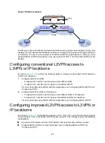
As shown in
, the access network is an MPLS L2VPN. PE 1 and PE 2 are PE devices in
the MPLS L2VPN. PE 1 is connected to VPN site 1. PE 2 is connected to the MPLS L3VPN/IP
backbone through PE 3. PE 3 acts as a PE in the MPLS L3VPN/IP backbone and as a CE in the
MPLS L2VPN at the same time.
A packet from VPN site 1 to VPN site 2 is forwarded as follows:
1.
A user in VPN site 1 sends a packet to PE 1.
2.
PE 1 adds an MPLS label to the packet and sends the packet through a PW to PE 2.
3.
PE 2 removes the MPLS label from the packet to obtain the original Layer 2 packet, and sends
the packet to the connected CE (PE 3).
4.
PE 3 looks up the routing table, and forwards the packet to the destination through the MPLS
L3VPN or IP backbone.


