111
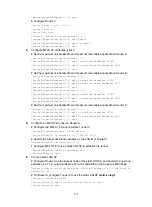
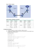
# Configure Router B as the transit node of the static CRLSP, and specify the incoming label as
20, next hop address as 3.2.1.2, outgoing label as 30, and bandwidth for the tunnel as 2000
kbps.
[RouterB] static-cr-lsp transit static-cr-lsp-1 in-label 20 nexthop 3.2.1.2 out-label
30 bandwidth 2000
# Configure Router C as the egress node of the static CRLSP, and specify the incoming label as
30.
[RouterC] static-cr-lsp egress static-cr-lsp-1 in-label 30
7.
Configure a static route on Router A to direct traffic destined for subnet 100.1.2.0/24 to MPLS
TE tunnel 0.
[RouterA] ip route-static 100.1.2.0 24 tunnel 0 preference 1
Verifying the configuration
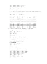
# Verify that the tunnel interface is up on Router A.
[RouterA] display interface tunnel
Tunnel0
Current state: UP
Line protocol state: UP
Description: Tunnel0 Interface
Bandwidth: 64kbps
Maximum transmission unit: 1496
Internet address: 6.1.1.1/24 (primary)
Tunnel source unknown, destination 3.3.3.3
Tunnel TTL 255
Tunnel protocol/transport CR_LSP
Output queue - Urgent queuing: Size/Length/Discards 0/100/0
Output queue - Protocol queuing: Size/Length/Discards 0/500/0
Output queue - FIFO queuing: Size/Length/Discards 0/75/0
Last clearing of counters: Never
Last 300 seconds input rate: 0 bytes/sec, 0 bits/sec, 0 packets/sec
Last 300 seconds output rate: 0 bytes/sec, 0 bits/sec, 0 packets/sec
Input: 0 packets, 0 bytes, 0 drops
Output: 0 packets, 0 bytes, 0 drops
# Display detailed information about the MPLS TE tunnel on Router A.
[RouterA] display mpls te tunnel-interface
Tunnel Name : Tunnel 0
Tunnel State : Up (Main CRLSP up)
Tunnel Attributes :
LSP ID : 1 Tunnel ID : 0
Admin State : Normal
Ingress LSR ID : 1.1.1.1 Egress LSR ID : 3.3.3.3
Signaling : Static Static CRLSP Name : static-cr-lsp-1
Resv Style : -
Tunnel mode : -
Reverse-LSP name : -
Reverse-LSP LSR ID : - Reverse-LSP Tunnel ID: -
Class Type : - Tunnel Bandwidth : -
Reserved Bandwidth : -
Setup Priority : 0 Holding Priority : 0


