410
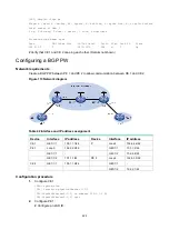
Figure 109 Network diagram
Configuration procedure
1.
Configure CE 1.
<CE1> system-view
[CE1] interface gigabitethernet 1/1/1
[CE1-GigabitEthernet1/1/1] ip address 10.1.1.1 24
[CE1-GigabitEthernet1/1/1] quit
2.
Configure CE 2.
<CE2> system-view
[CE2] interface serial 1/1/0
[CE2-Serial1/1/0] link-protocol ppp
[CE2-Serial1/1/0] ip address 10.1.1.2 24
[CE2-Serial1/1/0] quit
3.
Configure PE:
# Enable L2VPN.
<PE> system-view
[PE] l2vpn enable
# Configure the default next hop IP address as 10.1.1.1 on GigabitEthernet 1/1/1 (the interface
connected to CE 1). This interface does not need an IP address.
[PE] interface gigabitethernet 1/1/1
[PE-GigabitEthernet1/1/1] default-nexthop ip 10.1.1.1
[PE-GigabitEthernet1/1/1] quit
# Configure the IPCP proxy IP address as the IP address of CE 1 on Serial 1/1/0 (the interface
connected to CE 2). This interface does not need an IP address.
[PE] interface serial 1/1/0
[PE-Serial1/1/0] link-protocol ppp
[PE-Serial1/1/0] ppp ipcp proxy 10.1.1.1
[PE-Serial1/1/0] quit
# Create a cross-connect group named
vpn1
, create a cross-connect named
vpn1
in the group,
and enable interworking for the cross-connect.
[PE] xconnect-group vpn1
[PE-xcg-vpn1] connection vpn1
[PE-xcg-vpn1-vpn1] interworking ipv4
# Bind GigabitEthernet 1/1/1 and Serial 1/1/0 to the cross-connect.
[PE-xcg-vpn1-vpn1] ac interface gigabitethernet 1/1/1
[PE-xcg-vpn1-vpn1] ac interface serial 1/1/0
[PE-xcg-vpn1-vpn1] quit


