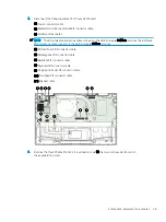
2.
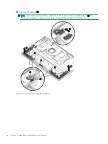
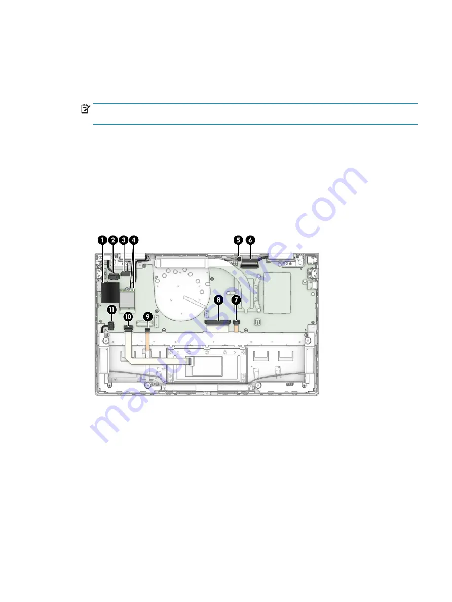
Disconnect the following cables from the system board:
(2) Power connector cable
(3) Webcam/microphone module ZIF connector cable
(4) WLAN antenna cables
NOTE:
The #1/white WLAN antenna cable connects to the WLAN module #1/Main terminal. The #2/black
WLAN antenna cable connects to the WLAN module #2/Aux terminal.
(5) Infrared board ZIF connector cable
(6) Display panel ZIF connector cable
(7) Backlight ZIF connector cable
(8) Keyboard ZIF connector cable
(9) Fingerprint reader ZIF connector cable
(10) Touchpad ZIF connector cable
(11) Speaker cable
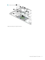
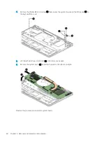
3.
Remove the three Phillips M2.0×2.3 broad head screws (1) that secure the system board to
the keyboard/top cover.
Component replacement procedures
59
Содержание ENVY x360 13
Страница 4: ...iv Safety warning notice ...
Страница 8: ...viii ...
Страница 40: ...Reverse this procedure to install the bottom cover 32 Chapter 5 Removal and replacement procedures ...
Страница 47: ...5 Remove the fan 4 Reverse this procedure to install the fan Component replacement procedures 39 ...
Страница 70: ...Reverse this procedure to install the heat sink 62 Chapter 5 Removal and replacement procedures ...

