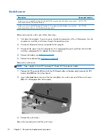
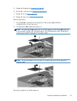
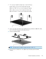
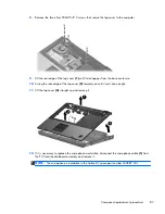
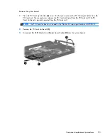
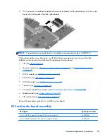
8.
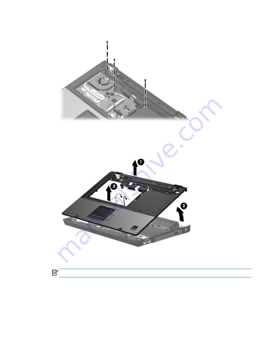
Remove the three Torx T8M2.5×9.0 screws that secure the top cover to the computer.
9.
Lift the rear edge of the top cover
(1)
until it disengages from the base enclosure.
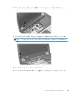
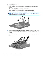
10.
Swing the rear edge of the top cover
(2)
toward you until it rests at an angle.
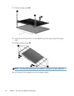
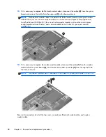
11.
Lift the top cover
(3)
straight up and remove it.
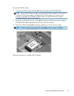
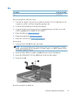
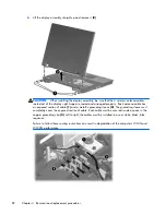
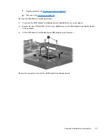
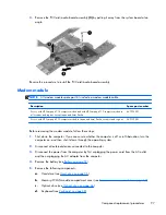
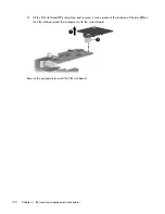
12.
If it is necessary to replace the microphone and cable, disconnect the microphone cable
(1)
from
the PC Card/audio board assembly and remove it.
NOTE:
The microphone is available in the Cable Kit, spare part number 443887-001.
Component replacement procedures
87
Содержание Compaq 6710b
Страница 4: ...iv Safety warning notice ...
Страница 9: ...Index 164 ix ...
Страница 10: ...x ...
Страница 23: ...2 External component identification Top components Buttons switches and fingerprint reader Top components 13 ...
Страница 34: ...Computer major components 24 Chapter 3 Illustrated parts catalog ...
Страница 124: ...Startup time 15 seconds Stop time 6 seconds 114 Chapter 6 Specifications ...
Страница 137: ...Where used 2 screws that secure the modem module to the PC Card audio board assembly Phillips PM2 5 3 0 screw 127 ...
Страница 178: ......