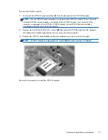
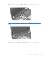
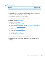
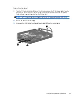
5.
Release the keyboard (see
Keyboard on page 68
).
6.
Remove the switch cover (see
Switch cover on page 74
).
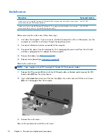
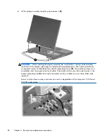
7.
Remove the fan (see
Fan on page 75
).
8.
Remove the heat sink (see
Heat sink on page 76
).
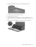
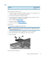
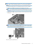
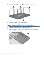
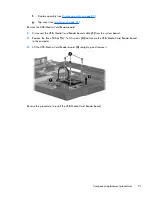
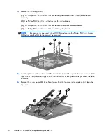
Remove the processor:
1.
Use a flat-bladed screwdriver to turn the processor locking screw
(1)
one-half turn
counterclockwise until you hear a click.
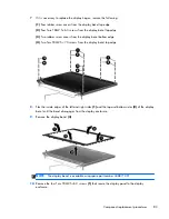
2.
Lift the processor
(2)
straight up and remove it.
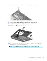
NOTE:
The gold triangle
(3)
on the processor must be aligned with the triangle
(4)
embossed
on the processor slot when you install the processor. The illustration below shows the processor
removal steps for the HP Compaq 6715 computer model.
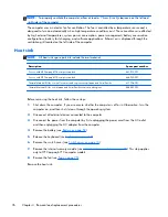
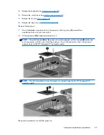
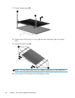
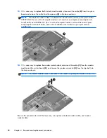
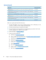
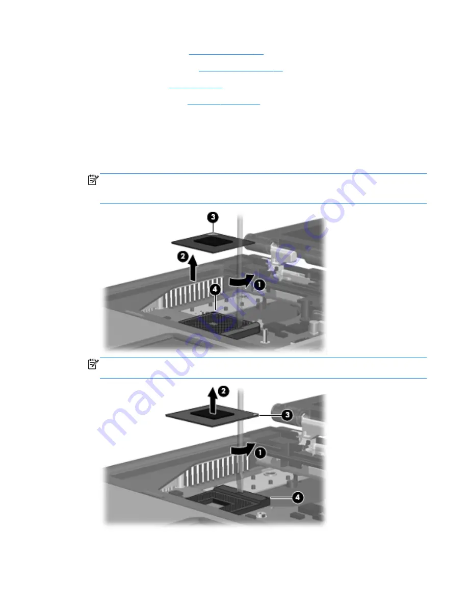
NOTE:
The illustration below shows the processor removal steps for the HP Compaq 6710
computer model.
Reverse this procedure to install the processor.
Component replacement procedures
79
Содержание Compaq 6710b
Страница 4: ...iv Safety warning notice ...
Страница 9: ...Index 164 ix ...
Страница 10: ...x ...
Страница 23: ...2 External component identification Top components Buttons switches and fingerprint reader Top components 13 ...
Страница 34: ...Computer major components 24 Chapter 3 Illustrated parts catalog ...
Страница 124: ...Startup time 15 seconds Stop time 6 seconds 114 Chapter 6 Specifications ...
Страница 137: ...Where used 2 screws that secure the modem module to the PC Card audio board assembly Phillips PM2 5 3 0 screw 127 ...
Страница 178: ......


