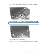
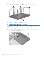
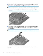
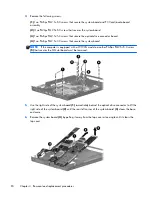

4.
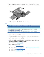
Remove the following screws:
(1)
Two Phillips PM2.5×5.0 screws that secure the system board and PC Card/audio board
assembly
(2)
One Phillips PM2.5×5.0 screw that secures the system board
(3)
Two Phillips PM2.5×5.0 screws that secure the optical drive connector board
(4)
Two Phillips PM2.5×3.0 screws that secure the system board
NOTE:
If the computer is equipped with a WWAN module, another Phillips PM2.5×5.0 screw
(5)
that secures the SIM slot board must be removed.
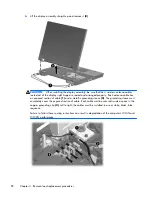
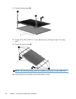
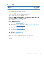
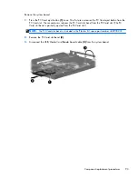
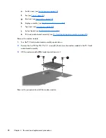
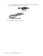
5.
Use the right side of the system board
(1)
immediately behind the optical drive connector to lift the
right side of the system board
(2)
until the rear left corner of the system board
(3)
clears the base
enclosure.
6.
Remove the system board
(4)
by pulling it away from the top cover at an angle until it clears the
top cover.
94
Chapter 4 Removal and replacement procedures
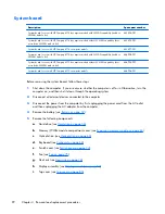
Содержание Compaq 6710b
Страница 4: ...iv Safety warning notice ...
Страница 9: ...Index 164 ix ...
Страница 10: ...x ...
Страница 23: ...2 External component identification Top components Buttons switches and fingerprint reader Top components 13 ...
Страница 34: ...Computer major components 24 Chapter 3 Illustrated parts catalog ...
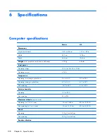
Страница 124: ...Startup time 15 seconds Stop time 6 seconds 114 Chapter 6 Specifications ...
Страница 137: ...Where used 2 screws that secure the modem module to the PC Card audio board assembly Phillips PM2 5 3 0 screw 127 ...
Страница 178: ......


