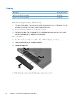
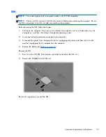
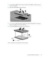
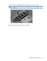

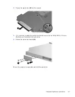
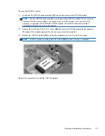
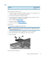
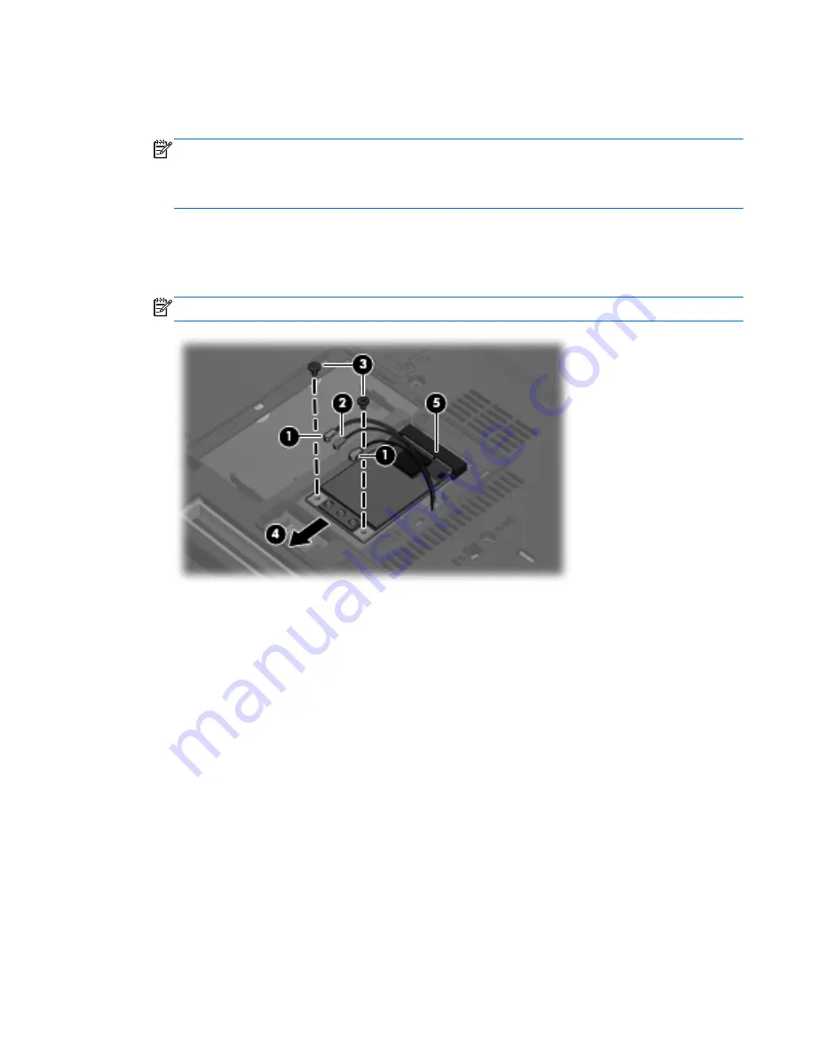
Remove the WLAN module:
1.
Disconnect the WLAN antenna cables
(1)
from the terminals on the WLAN module.
NOTE:
The black WLAN antenna cable is connected to the WLAN module “Main” terminal. The
white WLAN antenna cable is connected to the WLAN module “Aux” terminal. If the computer is
equipped with an 802.11a/b/g/n WLAN module, the yellow WLAN antenna cable
(2)
is
connected to the middle terminal on the WLAN module.
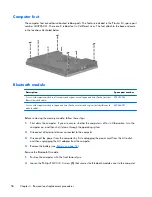
2.
Remove the two Phillips PM2.5×3.0 screws
(3)
that secure the WLAN module to the computer.
(The edge of the module opposite the slot rises away from the computer.)
3.
Remove the WLAN module
(4)
by pulling the module away from the slot at an angle.
NOTE:
WLAN modules are designed with a notch
(5)
to prevent incorrect installation.
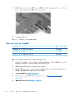
Reverse this procedure to install the WLAN module.
Component replacement procedures
65
Содержание Compaq 6710b
Страница 4: ...iv Safety warning notice ...
Страница 9: ...Index 164 ix ...
Страница 10: ...x ...
Страница 23: ...2 External component identification Top components Buttons switches and fingerprint reader Top components 13 ...
Страница 34: ...Computer major components 24 Chapter 3 Illustrated parts catalog ...
Страница 124: ...Startup time 15 seconds Stop time 6 seconds 114 Chapter 6 Specifications ...
Страница 137: ...Where used 2 screws that secure the modem module to the PC Card audio board assembly Phillips PM2 5 3 0 screw 127 ...
Страница 178: ......