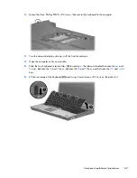
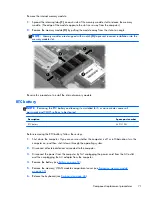
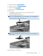
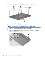
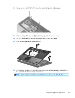
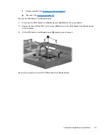
2.
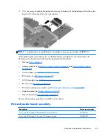
Remove the wireless antenna cables
(2)
from the routing channels and clips built into the top
cover.
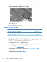
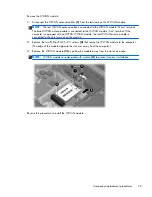
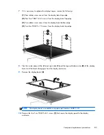
3.
Remove the two Torx T8M2.5×9.0 screws
(1)
that secure the display assembly to the computer.
NOTE:
The screw removed from the left hinge secures a ground loop
(2)
for the display panel
cable.
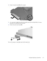
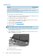
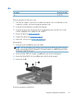
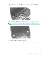
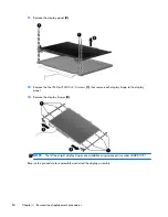
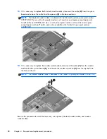
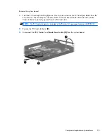
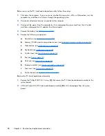
4.
Position the computer with the rear panel toward you.
5.
Remove the four Torx T8M2.5×9.0 screws
(1)
that secure the display assembly to the computer.
Component replacement procedures
81
Содержание Compaq 6710b
Страница 4: ...iv Safety warning notice ...
Страница 9: ...Index 164 ix ...
Страница 10: ...x ...
Страница 23: ...2 External component identification Top components Buttons switches and fingerprint reader Top components 13 ...
Страница 34: ...Computer major components 24 Chapter 3 Illustrated parts catalog ...
Страница 124: ...Startup time 15 seconds Stop time 6 seconds 114 Chapter 6 Specifications ...
Страница 137: ...Where used 2 screws that secure the modem module to the PC Card audio board assembly Phillips PM2 5 3 0 screw 127 ...
Страница 178: ......


