15.
Press
4
PEAK
SEARCH
5
on
the
sp ectrum
analyzer
and
read
the
marker
amplitude
on
the
display
.
If
an
an
tenna
is
connected
to
the
system,
the
an
tenna
factors
w
ould
b e
added
to
the
reading
to
give
actual
eld
strength
reading.
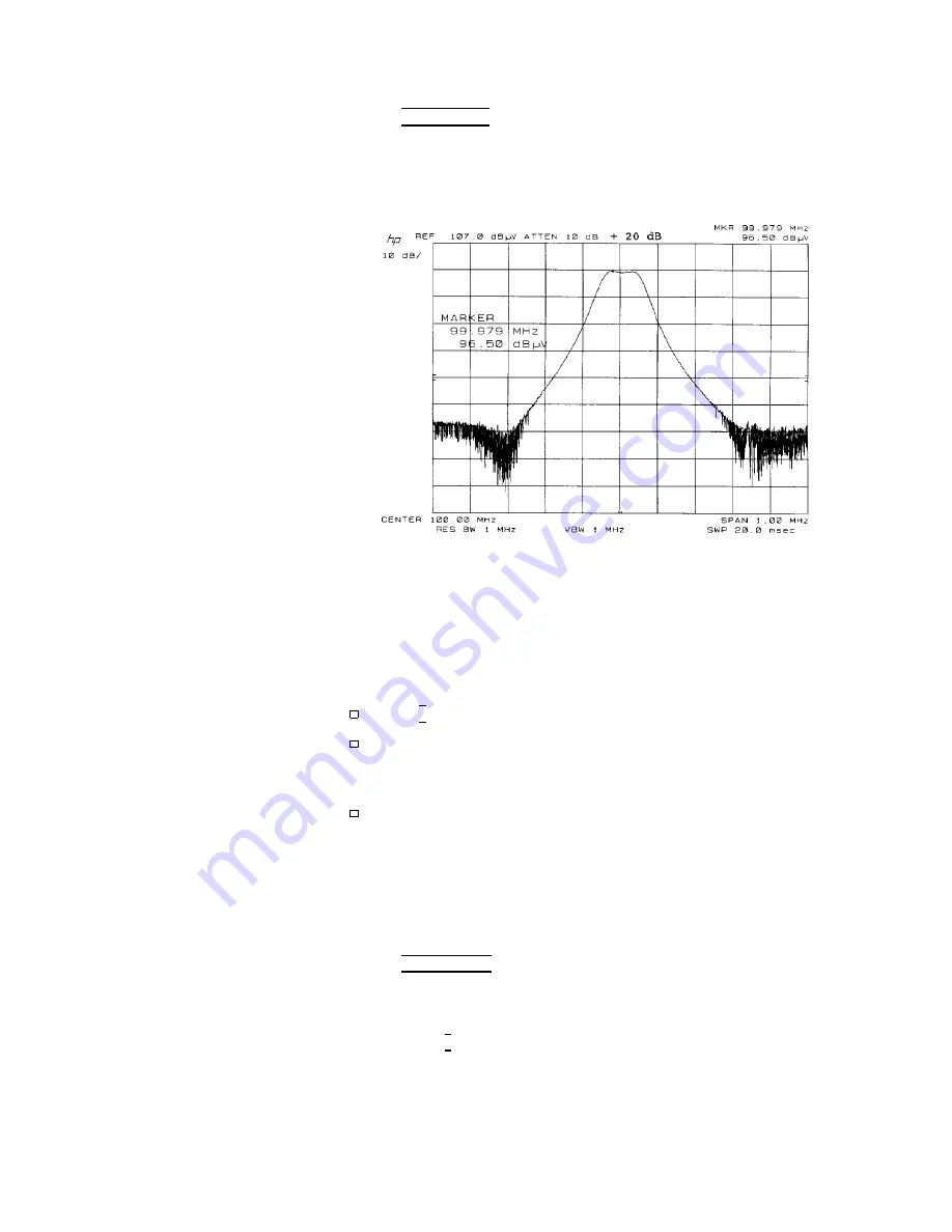
Refer
to
Figure
4-9.
Figure
4-9.
P
eak
Measurement
of
a
CW
Signal
16.
Use
the
3
dB
attenuator
in
the
preselector
to
c
hec
k
linearit
y
for
a
gain
compression
or
o
v
erload
condition.
The
attenuator
c
hanges
the
gain
b
y
adding
3
dB
of
attenuation.
If
the
amplitude
c
hanges
on
the
display
,
susp ect
an
o
v
erload
or
gain
compression.
If
this
test
indicates
an
o
v
erload
or
gain
compression:
Press
4
*
5
on
the
RF
preselector
to
add
10
dB
of
attenuation.
Repeat
the
linearit
y
c
hec
k
with
the
3
dB
attenuator.
Add
attenuation
if
necessary
un
til
the
o
v
erload
or
gain
compression
is
eliminated.
If
the
attenuation
is
increased,
the
receiv
er
should
b e
recalibrated
with
the
new
attenuator
setting
for
b est
accuracy
.
Example:
P
eak
Measuremen
t
(Broadband
Signal)
This
measuremen
t
uses
a
pulse
generator,
and
measures
the
15
MHz-to-16
MHz
region
where
conducted
measuremen
ts
are
p erformed.
The
results
are
sho
wn
in
Figure
4-10 .
1.
Press
4
INSTR
PRESET
5
on
the
quasi-p eak
adapter
and
on
the
preselector.
2.
Select
receiv
er
INPUT
1 .
3.
Press
the
0
4
5
k
ey
on
the
switch
driv
er
to
select
the
preamplier
BYP
ASS
path.
The
LED
in
the
k
ey
will
light.
4.
Connect
the
signal
source
to
receiv
er
INPUT
1 .
4-12
Making
Typical
Measurements
HP
8572A
EMI
Receiv
er
User's
Guide
Содержание 8572A
Страница 1: ...User s Guide HP 8572A EMI Receiver ABCDE HP Part No 08572 90003 Printed in USA April 1992 ...
Страница 8: ......
Страница 12: ......
Страница 25: ...Figure 1 2 Calibration Data Graph HP 8572A EMI Receiver User s Guide Calibrating Your Receiver 1 13 ...
Страница 54: ......
Страница 106: ......
Страница 112: ...Figure 4 5 Signal Detection and Processing 4 6 Making Typical Measurements HP 8572A EMI Receiver User s Guide ...
Страница 138: ......


