


Isolation
Chec
k
The
p o
w
er
sensor
is
disconnected,
the
3
dB
attenuator
is
connected
to
the
input
of
the
unit
under
test,
and
the
HP
85650A
quasi-p eak
adapter
is
put
in
to
b
ypass
mo
de.
The
input
signal
is
measured
with
the
EMI
receiv
er
system .
The
pulse
generator
is
set
to
dc
bias
the
mo
dulator
in
its
OFF
state
and
the
signal
is
measured
again.
The
t
w
o
readings
are
compared,
to
v
erify
that
the
mo
dulator's
isolation
is
greater
than
70
dBc.
This
ensures
accuracy
of
the
pulsed
RF
sp ectral
in
tensity
in
low
pulse
rep etition
frequencies
b
y
limiting
the
carrier
source
feedthrough
comp onen
t.
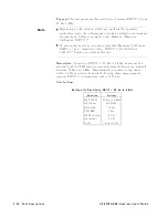
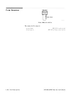
Pulsed
RF
Signal
The
pulse
generator
is
set
to
the
desired
pulse
rep etition
frequency
(PRF)
and
nominal
pulse
width.
The
HP
3335A
syn
thesizer/level
generator
amplitude
is
set
to
yield
the
CISPR-specied
sp ectral
in
tensity
of
the
main
lob
e
at
the
input
of
the
unit
under
test.
The
required
setting
for
the
HP
3335A
syn
thesizer/level
generator
is
determined
from
the
CISPR-sp
ecied
sp ectral
in
tensity
,
the
pulse
width,
and
the
reference
setting
determined
ab o
v
e.
If
the
HP
8116A
pulse/function
generator
is
used,
the
test
measures
the
n
ull
spacing
of
the
pulse
sp ectrum
to
set
the
pulse
width
more
accurately
than
the
nominal
v
alue
on
the
HP
8116A
pulse/function
generator.
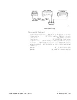
Pulse
Measuremen
t
The
HP
85650A
quasi-p eak
adapter
is
set
to
normal
mo
de
and
the
detector
is
turned
ON.
Time
is
allo w
ed
for
the
detector
to
settle.
The
pulse
mo
dulated
signal
then
is
measured
with
the
EMI
receiv
er
system .
The
pulse
rep etition
frequency
is
v
aried
to
measure
the
pulse
resp onse
at
the
CISPR
sp ecied
pulse
rep etition
frequencies.
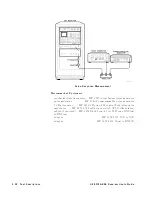
CW
Measuremen
t
The
pulse
generator
is
set
to
dc
bias
the
mo
dulator
in
its
ON
state.
The
HP
3335A
syn
thesizer/level
generator
amplitude
is
set
to
yield
60
dBuV
.
The
CW
signal
is
measured
with
the
EMI
receiv
er
system .
P
o
w
er
Sensor
Calibration
F
actors
\Optional:
En
tering
p o
w
er
sensor
calibration
factors"
in
Chapter
2
explains
the
requiremen
ts
for
en
tering
calibration
factors
for
the
p o
w
er
sensor
b eing
used.
3-32
T
est
Descriptions
HP
8572A
EMI
Receiv
er
User's
Guide
Содержание 8572A
Страница 1: ...User s Guide HP 8572A EMI Receiver ABCDE HP Part No 08572 90003 Printed in USA April 1992 ...
Страница 8: ......
Страница 12: ......
Страница 25: ...Figure 1 2 Calibration Data Graph HP 8572A EMI Receiver User s Guide Calibrating Your Receiver 1 13 ...
Страница 54: ......
Страница 106: ......
Страница 112: ...Figure 4 5 Signal Detection and Processing 4 6 Making Typical Measurements HP 8572A EMI Receiver User s Guide ...
Страница 138: ......


