


42
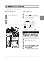
3-5 Setting the Scoring Rollers
Lower the upper scoring roller.
- Turn the knob clockwise to lower the upper
scoring roller.
- To reach the standard setting, turn the knob
one rotation counterclockwise from the stop.
Adjust so that there is a small gap
between the upper and lower adjustable
scoring rollers. You should be able to
move the upper adjustable roller a bit
with your finger.
Close the right safety cover.
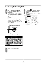
Press the
(Setting Position)
button on the Single Operation
Screen.
- The adjustable scoring rollers move to the set-
ting positions.
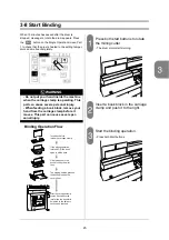
CAUTION
If the scoring pressure is so strong so
that the scoring roller does not rotate,
the machine may be damaged when
performing a changeover. Before each
changeover, check with your finger to
ensure that the scoring rollers rotate
smoothly.
Upper Adjustable Scoring Roller
Standard Gap
Lower Adjustable Scoring Roller
Содержание BQ-270
Страница 60: ...54...
Страница 102: ...96...
Страница 120: ...114 9 4 Option Extractor VS 270 1 pc Weekly Timer 1 pc...