background image

SWIFT® Smart Wireless Integrated Fire Technology Manual —

 P/N LS10036-000SK-E:G  4/13/2020

53

Appendix D: LED Indicators

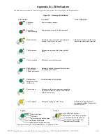
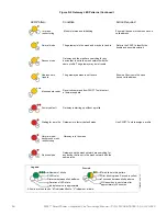
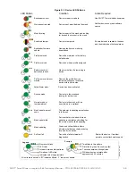
The LED indicator patterns for the wireless gateway and wireless devices are shown in the tables below. 

LED Pattern

Condition

Action Required

Bootloader 
normal

Bootloader 
Firmware update

Mesh formation

Profile removed

Profile accepted

Normal mode/
background mesh 
restructuring

Rescue mode

Device is ready to update

New application code is being downloaded

Gateway is forming the mesh and looking for 
devices that are not in the mesh

Wait until all devices join the mesh 
and then terminate mesh formation

Gateway has returned to the factory default 
state

Gateway is now profile assigned

Normal operation of the gateway

Gateway and the mesh network are searching 
for any device that is not in the mesh network 
with the same profile

Legend

Number of blinks

LED color

Interval between blink patterns

Duration of LED state

Indicates value is approximate

Two blinks in this pattern

First blink is green, Second is yellow

7 seconds between blink patterns

Will transition to next state after 
approximately 20 minutes

Example:

All units are in seconds. “M” indicates Minute. “V” indicates Variable.

led

gat

e1_

4.

0.w

m

f

6

20

M

1

5

10

18

12

3

M

Solid

7

20

M

10

1

Profile assigned

Gateway is starting up with a profile

Mesh update in 
progress/Mesh 
update -parent node

Gateway is updating the mesh/Parent nodes 
are updating child nodes

4

M

Solid

Activate both magnetic sensors 
simultaneously within 10 seconds to 
remove a profile

Figure D.1  Gateway LED Patterns

Содержание SILENT KNIGHT SWIFT

Страница 1: ...SWIFT Smart Wireless Integrated Fire Technology Instruction Manual Document LS10036 000SK E Rev G 4 13 2020 ECN 150692 ...

Страница 2: ...f detector may not provide adequate warning of a fire Smoke detectors cannot be expected to provide adequate warning of fires caused by arson children playing with matches especially in bedrooms smoking in bed and violent explosions caused by escaping gas improper storage of flammable materials etc Heat detectors do not sense particles of combustion and alarm only when heat on their sensors increa...

Страница 3: ...lectronic assemblies prior to any drilling filing reaming or punching of the enclosure When possible make all cable entries from the sides or rear Before making modifications verify that they will not interfere with battery transformer or printed circuit board location Do not tighten screw terminals more than 9 in lbs Over tighten ing may damage threads resulting in reduced terminal contact pressu...

Страница 4: ...ware and the appropriate version for a specific application Documentation Feedback Your feedback helps us keep our documentation up to date and accurate If you have any comments or suggestions about our online Help or printed manuals you can email us Please include the following information Product name and version number if applicable Printed manual or online Help Topic Title for online Help Page...

Страница 5: ...ration and Programming 15 2 8 1 Assign a Profile 15 2 8 2 Remove a Profile 16 Remove a Profile from a Gateway using SWIFT Tools 16 Remove a Profile from a Gateway without using SWIFT Tools 17 2 8 3 Create a Mesh Network 17 2 8 4 SLC Configuration 18 2 9 Operations 19 2 9 1 Modes of Operation 19 Start up Mode 19 Factory Default Mode 19 Profile Configured 19 Mesh Formation 19 Initial Mesh Restructur...

Страница 6: ...ble Conditions 36 Trouble Conditions with Fire Protection 36 Trouble States without Fire Protection 36 Section 4 W SYNC Wireless Synchronization Module 38 4 1 Description 38 4 2 Wiring 38 4 2 1 FACP 38 4 2 2 HPFF8 HPFF12 NAC Expander 39 Section 5 W USB Adapter 40 5 1 Introduction 40 5 2 Agency Approvals 40 5 2 1 FCC 40 5 2 2 Federal Institute of Telecommunications 40 5 3 Specifications 41 5 3 1 El...

Страница 7: ...ing LED Indicators 50 C 3 Testing the Wireless Network 50 C 3 1 Network Topology 51 Parent Child Devices 51 Orphan Devices 51 Class A Compliance 51 C 3 2 History Events 51 C 3 3 Network Snapshots 51 C 3 4 Network Statistics 51 C 3 5 Device Attributes 51 Appendix D LED Indicators 53 Appendix E Firmware Upgrade Downgrade Instructions 58 E 1 W USB Adapter Upgrade Procedure 58 E 2 Mesh Network Firmwar...

Страница 8: ...capabilities Ensure the latest version of SWIFT Tools is installed for proper functionality Systems running version 4 0 and higher will require device tamper to remove a profile return to factory default with a 60 minute timeout have option to enable disable max gateway trouble reporting require device tamper to upgrade the firmware on individual devices Systems running 4 0 and higher will not be ...

Страница 9: ...ndations When using SWIFT Tools to update the firmware of the gateway or devices ensure updates are performed in a secure location where no eavesdropping on the wireless signals is possible Ensure the PC running SWIFT Tools has full disk encryption Full encryption of any backed up data is also recommended The wireless gateway should be secured in a location which is only accessible to authorized p...

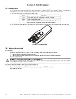
Страница 10: ...two conditions 1 This device may not cause harmful interference and 2 This device must accept any interference received including interference that may cause undesired operation 3 FCC ID PV3WFSGW 2 2 2 Federal Institute of Telecommunications This device utilizes the Honeywell915 rev A radio module and complies with IFETEL standard s IFT RCPHOSW14 1983 2 3 Specifications Following are the specifica...

Страница 11: ... LEDs on the gateway blink in the same pattern to allow the LED to be viewed from any angle LED patterns are explained in Appendix D 2 6 Installing the Gateway 2 6 1 Before Installing Choose a location for the gateway that is clean dry and vibration free The area should be readily accessible with sufficient room to eas ily install and maintain the gateway Metal obstructions impede the radio freque...

Страница 12: ...plate can be mounted to any flat surface and the wiring can be connected via the knockout points in the mounting plate To mount the gateway 1 Pull the wiring through the opening in the mounting plate 2 Mount the mounting plate to the junction box or ceiling See Figure 2 3 below 3 Connect field wiring to the terminals as described in Section 2 7 2 4 Connect necessary jumpers where applicable as des...

Страница 13: ...nded For wiring connections 1 Strip about 3 8 of insulation from the end of the wire 2 Slide the stripped end of the wire under the appropriate terminal and tighten the screw Figure 2 4 Attaching Cover to Mounting Plate 2 3 wmf locating pin locating pin locating pin NOTE Do not loop the wire under the screw terminals Figure 2 5 WSK WGI Mounting Plate Terminal Layout A7 SLC Out In A6 SLC In Out A5 ...

Страница 14: ...ts including Class A applications and applications that use isolator modules 2 7 4 Gateway Powered by an External Regulated 24VDC Source To power the gateway using an external regulated 24VDC source connect the gateway as described in the table and drawing below Terminal Pins Description A5 and A7 SLC Common SLC Output A5 and A6 SLC Common SLC Input A4 and A5 Jumper selection to enable power from ...

Страница 15: ...he gateway using SWIFT Tools 1 Connect the W USB device to your laptop For more information on the W USB adapter refer to Section 5 W USB Adapter on page 40 2 Launch SWIFT Tools Refer to Appendix A for more information 3 From the Home Screen select the Create Mesh Network function 4 Create a new profile or Import an existing profile as required 5 Select and open the profile to be assigned to the g...

Страница 16: ...om a Gateway using SWIFT Tools 1 Connect the W USB adapter to your laptop For more information on the W USB device refer to Section 5 W USB Adapter on page 40 2 Launch SWIFT Tools Refer to Appendix A SWIFT Tools for more information on launching the SWIFT Tools application 3 From the Home Screen select the Site Survey Create Mesh Network or Diagnostics function 4 Click Operations and select Set de...

Страница 17: ...cating that the profile is removed 2 8 3 Create a Mesh Network To create a mesh network using the SWIFT Tools perform the following steps 1 Connect the W USB device to your laptop For more information on the W USB adapter refer to Section 5 W USB Adapter on page 40 2 Launch SWIFT Tools Refer to Appendix A for more information 3 From the Home Screen select the Create Mesh Network function 4 Proceed...

Страница 18: ... other devices to join 11 Start Mesh Restructuring by either waiting or clicking Start Once Restructuring is initiated the progress displays When Mesh Restructuring is complete the following success message is shown For further operating instructions refer to Section 2 9 Operations 2 8 4 SLC Configuration The gateway communicates with the control panel via the SLC is only compatible with Gateway f...

Страница 19: ...is removed from the gate way it will return to Factory Default mode Profile Configured The gateway enters the profile configured mode once a profile is assigned by SWIFT Tools Profile configured mode is a temporary mode before the gateway transitions to mesh formation or normal mode The gateway does not provide fire protection in the profile configured mode While in the profile configured mode the...

Страница 20: ...last device is rescued and returns to normal mode The gateway does not report troubles during rescue mode but reports Rescue to the communicator display of the SWIFT Tools application Mesh Restructuring Mode In addition to the initial mesh restructuring mode mesh restructuring is automatically performed after any restoration of communication to a device or to recover from a link failure Class A fa...

Страница 21: ... gateway 1 Click Lock The Gateway Password screen is displayed 2 Enter the verification password in the Verification Password field and click OK 3 A Hall Sensor Activation window displays The LED on the gateway blinks yellow indicating the gateway is waiting for hall sensor activation 4 Place a magnet on either of the gateway sensors within 120 seconds 5 The LED blinks normal upon hall sensor acti...

Страница 22: ... GATEWAY trouble is generated when a fifth gateway mesh is detected and the maximum limit is exceeded When there is a MAX GATEWAY trouble present in the system it is permitted to turn off MAX GATEWAY trouble reporting after completing the following evaluation method with successful results For the result to be successful the signal strength between devices in any one mesh must be at least 20 dB st...

Страница 23: ...air of test devices Refer to Appendix B Site Survey for instructions on how to perform a site survey Use SWIFT Tools to identify the signal strength link quality for each of the four link tests and record these values 5 Use network statistics from the gateway to determine link strength between edge devices in each mesh Figure 2 21 Perform a Link Test with the Fifth Mesh Mesh 1 Mesh 2 Mesh 5 Mesh 4...

Страница 24: ...ach mesh 9 Compare that lowest value from each mesh to the corresponding link values in step 4 10 If the values in step 8 are at least 20dB higher that the values in step 4 continue to step 11 If they are not installation of Mesh 5 is not allowed 11 Repeat this process from step 4 identifying device pair locations for each mesh Mesh 1 to Mesh 2 Mesh 1 to Mesh 3 Mesh 1 to Mesh 4 Mesh 2 to Mesh 3 Me...

Страница 25: ...tion 3 From the Home Screen select the Diagnostics function 4 Select a Gateway from the communicator panel 5 Click View Mesh SWIFT Tools will display Lock Unlock option Refer to Section 2 9 3 on page 20 for additional information 6 Click Advanced Functions A drop down list is displayed 7 Click Max Gateway troubles On The Max Gateway troubles screen is displayed 8 Click Turn off reporting The troub...

Страница 26: ...FT Tools application Refer to Appendix A SWIFT Tools for more information 3 From the Home Screen select the Diagnostics function 4 Select the desired gateway from the communicator panel 5 Click View Mesh SWIFT Tools will display Lock Unlock option Refer to Section 2 9 3 on page 20 for additional information 6 Click Advanced Functions A drop down list is displayed 7 Click Weak links troubles On The...

Страница 27: ... time All devices will retain the profile information but will be removed from the mesh The devices will not send or receive any wireless communication until the set time expires or the device is rebooted The mesh network can be reformed at the end of the silence period or after the device is restarted Silence Mesh Network Using SWIFT Tools To silence the mesh network 1 Connect the W USB device to...

Страница 28: ...ate wired notification appliances anywhere in the system and wireless input modules may be programmed to activate wireless output devices including relay modules sync modules and AV devices within the same wireless mesh network Wireless input modules are not permitted to be programmed to activate wireless outputs in another wireless mesh Wireless detector programming is not restricted since the al...

Страница 29: ...ming the initial identification and assignment of optimal communication paths for the mesh network The wireless system is not able to provide fire protection during this time No action needed The duration of this event correlates to the number of devices in the mesh A fully loaded mesh may take up to 5 minutes to restructure NO PROFILE Non latching The gateway is in the factory default state and i...

Страница 30: ...le Relay Module FCC ID AUBWFSRM The wireless relay module is powered by four CR123A batteries It provides the system with a dry contact output for activating a variety of auxiliary devices such as fans dampers control equipment etc Addressability allows the dry contact to be activated either manually or through panel programming on a select basis The module has an LED to indicate the activation an...

Страница 31: ...ion Pattern OFF OFF Off ON OFF Strobe Only Audible Silenced ON ON Strobe Audible active OFF ON Magnet Test mode Strobe audible activate when magnet is placed on the unit NOTE To configure an audible visual unit to silence only the audible component with a signal silence command configure both addresses to activate for the alarm condition the base address shall be non silenceable and the base 1 sha...

Страница 32: ... on the device within approximately 20 feet of the laptop running SWIFT Tools 7 Ensure that the Scan On selection box in the communicator panel is checked Specification Data Radio Frequency Lower ISM Band 902 928 MHz Maximum power output 17dBm Minimum signal strength level needed at the receiver for a primary path with weak link trouble reporting enabled 55dBm Minimum signal strength level needed ...

Страница 33: ...tic sensor on the gateway Repeater The SWIFT Network does not require the use of a dedicated repeater as all wireless devices act as repeaters When the repeater function is needed in a location where no specific fire function is required a wireless monitor module or another device can be installed to act as a repeater 3 5 3 Restoring a Device to Factory Default SWIFT Tools must be used to restore ...

Страница 34: ...sor on the detector and place powered on devices that are to be reset in range of the W USB adapter Once the device has been tampered or hall sensor activated a 60 minute countdown will start for profile removal Figure 3 5 Magnetic Sensor on a Detector magnetdet wmf LED LED Magnet test switch Tamper magnet Figure 3 6 Magnetic Sensor on a Module ma gn et mo n w m f Magnetic sensor ...

Страница 35: ...n the communicator section of SWIFT Tools A device in site survey will not communicate with SWIFT Tools and will be listed as offline in the communi cator section For more information on performing a site survey refer to Appendix B Profile Assigned Mode In this mode devices are associated with the gateway but are not active participants in the mesh network A device that is not in the tam pered sta...

Страница 36: ...device is tampered it drops out of the mesh network and attempts to rejoin as soon as the batteries are replaced and the tamper event is cleared If the device has dropped from the mesh prior to the tamper event a system reset has to be issued to clear the low battery trou ble The panel displays LOW BATTERY or LOW BATT during a low battery condition Weak Link The weak link trouble denotes a connect...

Страница 37: ...For a module ensure that there is a magnet in the cover plate and it is securely fastened to the device in the correct orientation Once the tamper event is cleared the LEDs in the device turn on steady for 2 5 seconds in the following color patterns that denote the battery status Green All the four batteries are installed and fresh The device has a minimum one year of normal operation Yellow All t...

Страница 38: ...ro nized output wiring must be contained in the common enclosure of modules or wired in conduit in enclosures mounted within 20 feet of each other in the same room with wiring in conduit When Class A zones are used power supply wiring must be contained in the common enclosure with the W SYNC or the power supply and W SYNC must be in enclosures within 20 feet of each other in the same room with wir...

Страница 39: ... the DIP switches on the HPFF8 HPFF12 as follows SW1 OFF SW2 OFF SW3 OFF SW4 OFF SW5 ON SW6 OFF Wire the W SYNC to the HPFF8 12 as follows TB3 TB4 TB1 TB2 REF REF IN IN OUT IN OUT IN OUT OUT SIGNAL 1 SIGNAL 2 BATT BATT A N O N C COMM N O N C COMM AC FAIL TROUBLE 1L1 1L2 2L1 2L2 3L1 3L2 4L1 4L2 A HPFF8 HPFF12 W SYNC 3 9KΩ ELR Figure 4 2 W SYNC Wiring to HPFF8 HPFF12 C NC 24VDC Power power supply tr...

Страница 40: ...peration is subject to the following two conditions 1 This device may not cause harmful interference and 2 This device must accept any interference received including interference that may cause undesired operation FCC ID PV3WFSADPT 5 2 2 Federal Institute of Telecommunications This device utilizes the Honeywell915 rev A radio module and complies with IFETEL standard s IFT RCPSYWU14 1829 Color Des...

Страница 41: ...tor open 3 8 in 96 2 mm Thickness on connector side 0 5 in 13 mm Thickness on antenna side 0 3 in 8 4 mm Width 1 2 in 31 2 mm Weight 0 7 oz 19 5 g 5 3 4 Environmental Specifications Humidity 10 RH 93 RH non condensing Maximum operating temperature 32 F 122 F 0 C 50 C Storage temperature 14 F 140 F 10 C 60 C 5 4 Driver Installation To install a driver 1 Insert the W USB adapter into the PC The W US...

Страница 42: ...t Update Driver Software 3 Select the Browse my computer for driver software option 4 The Browse dialog box appears Click Browse Navigate to the folder C Program Files Honeywell Device Driver Click Next Figure 5 3 Update Driver Software devcemanager8 jpg Figure 5 4 Browse Computer for Driver Software devcemanager9 jpg Figure 5 5 Browse Folder for Driver Software devcemanager10 jpg ...

Страница 43: ...management screen under Ports If SWIFT Tools detects an incompatible W USB adapter connected it will prompt a message to update the W USB adapter firmware If you get this error message update the W USB adapter through the Firmware Update feature in the Operations section of SWIFT Tools Figure 5 6 Driver Software Update Confirmation devcemanager11 jpg Figure 5 7 New Communications Port devcemanager...

Страница 44: ...ing Microsoft Windows Minimum system requirements are listed below A 2 Launching SWIFT Tools To launch SWIFT Tools 1 Click Start point to All Programs click SWIFT Tool and then SWIFT Tool The following screen is displayed Alternatively SWIFT Tools can be opened through a shortcut located on the desktop 2 The SWIFT Tools screen is displayed Create a new jobsite or open an existing one A 2 1 Creatin...

Страница 45: ... duration communication session that times out after a period of inactivity To connect to the gateway via SWIFT Tools perform the following steps A 3 1 Accessing a Locked Gateway 1 Select the desired gateway 2 Enter a valid password into SWIFT Tools 3 SWIFT Tools will show a 120 second timer 4 Use a magnet to activate either of the two sensors on the gateway within the 120 second time frame The LE...

Страница 46: ...ity test 1 Remove the batteries from the devices that will be used for the site survey and set the SLC address To set an SLC address use a flathead screwdriver to adjust the rotary switches on the device 1 For the first device used in a site survey set the SLC address to 001 2 For each subsequent device use the next highest SLC address up to address 150 For example the first device was set to 001 ...

Страница 47: ... etc Each device will conduct the link quality test as described above then transition to the RF scan test 5 minutes after the last link quality test is performed to or from that device If several devices are being tested it is possible that some devices will start and complete the link test and progress to the RF scan test while other devices are finishing the link quality test The RF Scan test m...

Страница 48: ... that have completed a link quality test or by rebooting devices that have completed an RF scan test 2 Plug the W USB adapter into the laptop PC where SWIFT Tools has been installed 3 Bring the devices within a range of approximately 20 feet from the W USB adapter connected to the laptop PC 4 Log into SWIFT Tools and retrieve the data CAUTION SITE SURVEY RESULTS WILL BE REPLACED DO NOT CLEAR THE T...

Страница 49: ...er condition is cleared Check to ensure the tamper magnet has not become dislodged Check the device spacing and the range from the device to the mesh A site survey link test can be used to verify connectivity from one location to another Mesh restructuring does not end The gateway mesh network appears to be stuck in mesh restructuring Use SWIFT Tools to investigate for the presence of interference...

Страница 50: ...s Verify the device or gateway is powered on and in a state that supports SWIFT Tools communication For instance a device in the mesh network does not communicate to SWIFT Tools It communicates to the gateway A device that has completed a site survey does not communicate to SWIFT Tools until it returns to the pending site survey state or factory default state Move the W USB adapter in range of gat...

Страница 51: ...ess network can be retrieved and viewed using SWIFT Tools for troubleshooting purposes This report pro vides information on when the device gets connected with the wireless network mode change and slot change details C 3 3 Network Snapshots Network snapshots can be retrieved and viewed using SWIFT Tools for troubleshooting purposes The network snapshot helps to ana lyze how the wireless network is...

Страница 52: ...52 SWIFT Smart Wireless Integrated Fire Technology Manual P N LS10036 000SK E G 4 13 2020 Notes ...

Страница 53: ...eway is now profile assigned Normal operation of the gateway Gateway and the mesh network are searching for any device that is not in the mesh network with the same profile Legend Number of blinks LED color Interval between blink patterns Duration of LED state Indicates value is approximate Two blinks in this pattern First blink is green Second is yellow 7 seconds between blink patterns Will trans...

Страница 54: ... blink patterns Will transition to next state after approximately 20 minutes Example ledgate2_4 0 wmf Ensure all devices in the mesh have a valid address Use SWIFT Tools to assign a profile Figure D 2 Gateway LED Patterns Continued Rescue mode Gateway and the mesh are searching for any device that is not in the mesh network with the same profile The gateway may be in trouble 12 3M Normal mode back...
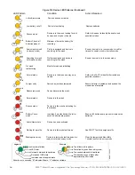
Страница 55: ...m device count and software version Device is tampered Solid Solid 8 6 20M 15 5 1 10 2 5 Ensure detector is seated in the base and the module has the faceplate on 12 3M Rescue mode Device is in the mesh and looking for lost devices Normal mode or tested walktest Device is in the mesh or it has been tested in a walktest 7 20M Figure D 3 Device LED Patterns Use SWIFT Tools to initiate download Self ...

Страница 56: ...ormation mode Discovered mesh Device discovered the mesh Solid 2 5 90 3 Ensure the mesh is in formation mode 25 6 5M Refer to the FACP to identify the trouble and possible resolution 18 4 Ensure detector is seated in the base and the module has a faceplate Solid 6 Solid Waiting for a profile Pending site survey Active Alarm state Battery Check weak Device is in factory default mode Device is in fa...

Страница 57: ...SWIFT Smart Wireless Integrated Fire Technology Manual P N LS10036 000SK E G 4 13 2020 57 Notes ...

Страница 58: ...adapter Ensure the latest version of SWIFT Tools is installed SWIFT Tools and firmware can be downloaded from www silentknight com There are multiple bin files with the zip file Save the files to a folder The W USB adapter will auto update if the SWIFT Tools and W USB adapter versions are incompatible 1 Insert the W USB adapter into the PC and launch SWIFT Tools A pop up message confirming the W U...

Страница 59: ...re Update screen is displayed 5 Select the Service Pack from the Firmware Version drop down box or click Choose File and then browse for the service pack zip file from your local drive and click OK 6 Select the respective gateway and follow the on screen instructions and wait until the mesh feasibility check finishes 7 Click Update As the mesh update progresses the status bar will update E 3 Devic...

Страница 60: ...cedure Phase 1 Mesh upgrade preparation SWIFT Tools must stay in communication with the gateway during the mesh upgrade preparation phase The user will initiate the upgrade process via SWIFT Tools and SWIFT Tools will proceed to automatically update the SLC application code of the gateway the RF application code of the gateway and transfer the new device application code to the gateway The user ma...

Страница 61: ...file configure 19 profile distribution 18 programming 15 remove profile 17 rescue mode 20 restrictions 28 RF interference 28 silence network 27 SLC configuration 18 SLC connections 14 specifications 10 start up 19 weak link trouble 26 wiring 13 H heat detector 30 I initial mesh restructuring 20 initial mesh restructuring mode 36 initialization 37 installing devices 32 interference 28 isolator modu...

Страница 62: ...tions 14 smoke detector 30 specifications 10 41 spectrum 28 RF 28 spread 28 spread spectrum 28 start up 19 SWIFT Tools 44 50 T tamper 37 clear 37 testing 50 transmission 20 trouble condition 20 26 trouble messages 29 trouble reporting disable 26 troubleshooting 49 U unlock 20 upgrade mesh 20 W walkie talkie mode 29 weak link 36 trouble reporting 26 wireless devices 30 wireless gateway 10 wiring 13...

Страница 63: ...T TO THE PRODUCTS TRADEMARKS PROGRAMS AND SERVICES RENDERED BY MANUFACTURER INCLUDING WITHOUT LIMITATION INFRINGEMENT TITLE MERCHANTABILITY OR FITNESS FOR ANY PARTICULAR PURPOSE MANUFACTURER SHALL NOT BE LIABLE FOR ANY PERSONAL INJURY OR DEATH WHICH MAY ARISE IN THE COURSE OF OR AS A RESULT OF PERSONAL COMMERCIAL OR INDUSTRIAL USES OF ITS PRODUCTS This document constitutes the only warranty made b...

Страница 64: ...LS10036 000SK E G 01 19 2020 Honeywell International Inc Honeywell Silent Knight 12 Clintonville Road Northford CT 06472 1610 203 484 7161 www silentknight com ...

Отзывы: