background image

® U.S. Registered Trademark
Copyright © 1997 Honeywell Inc.  •  All Rights Reserved

74-2566

Excel 10 Hand Held Tool

PRODUCT DATA

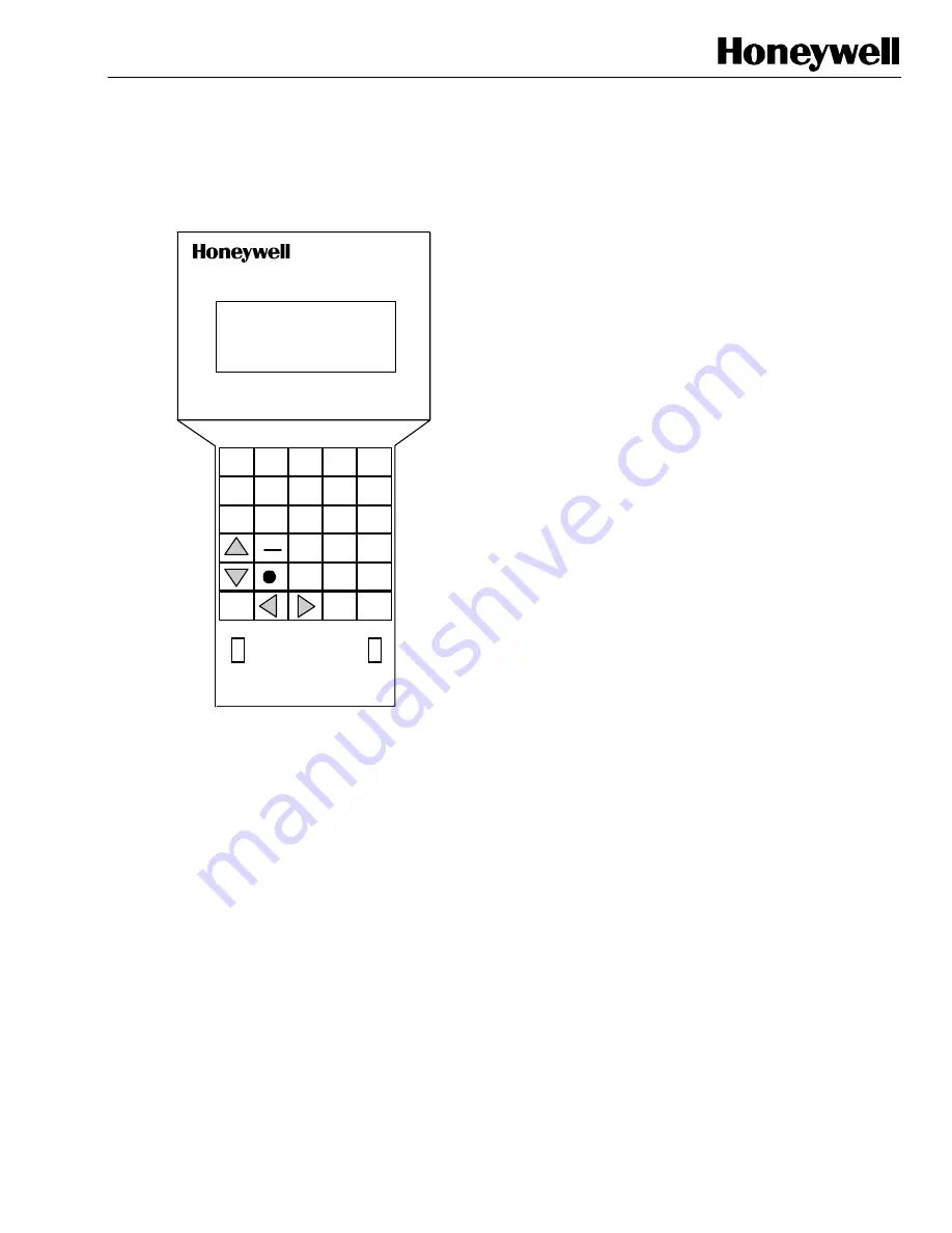
R O W   O N E
R O W   T W O

R O W   T H R E E
R O W   F O U R

E N T E R


T O P

M E N U

0

2

5

6

3

7

8

9

4

1

A

B

C

D

E

F

P R E V

R E -

F R E S H

A B O R T

O N / O F F

C A B L E   P O R T

D C   A D A P T E R

J A C K

T E R M I N A T O R

          S W I T C H

E - B U S

D C

A D A P T E R

N E T W O R K

T E R M I N A T O R

P O W E R

O N

O F F

M E N U

O N

O F F

N E T W O R K

N E T W O R K

S W I T C H

FEATURES

Four Line by 20 Character LCD display with 30 position
keypad.

Operates from a DC adapter or an external battery
pack.

Operates for 12 hours without battery recharge.

Ambient temperature range: 40 to 120 °F (4 to 49 °C).

Uses the part number 205979 SLTA Connector Cable
that connects directly to Excel 10 Controllers.

APPLICATION

The S7751A Hand Held Tool (HHT) is used with W7751A,C,E Excel 10 VAV 1 Controllers. (NOTE: The HHT phase 1 cannot
communicate with the phase 2 devices, such as; FCU, CVAHU, RIO and VAV 2. The HHT can be used to view or modify
points, setpoints or parameters, perform diagnostics, and balance Excel 10 controllers. In stand-alone applications (not used
in conjunction with Care/LiveCare), the HHT performs the application configuration (hardware inputs and outputs and
software points) and balancing.

Содержание S7751A

Страница 1: ...al battery pack Operates for 12 hours without battery recharge Ambient temperature range 40 to 120 F 4 to 49 C Uses the part number 205979 SLTA Connector Cable that connects directly to Excel 10 Controllers APPLICATION The S7751A Hand Held Tool HHT is used with W7751A C E Excel 10 VAV 1 Controllers NOTE The HHT phase 1 cannot communicate with the phase 2 devices such as FCU CVAHU RIO and VAV 2 The...

Страница 2: ... ID 9 Neuron ID 10 Push Button ID 10 Stand Alone ID 10 Service Excel 10 10 I O Points 11 Logical Group 11 Temp Setpoints 13 Diagnostic Points 14 Commandable Points 14 Alarms 17 Current Alarms 17 Alarm Log 19 Test Mode 19 Damper 19 Reheat Valve 20 Reheat Stages 21 Fan 22 Calibrate Temp Sens 22 Controller Version 23 Balance VAV 23 Normal 24 Zero 24 Maximum 25 Minimum 25 Full Open 26 Defaults 26 Conf...

Страница 3: ...Night Purge 34 Morning Warm up 34 Pressurization 35 Depressurization 35 Closed Pos Offset 35 Cooling Gains 35 Reheat Gains 36 Demand Limit Offset 36 Flow Tracking Offset 36 HHT Functions 37 Assign Node Numbers 37 Change Authorization 37 Balance VAV 38 Operator Level 38 Modify Passwords 38 Balance VAV 38 Operator Level 39 Clear Node Numbers 39 Engineering Units 40 ...

Страница 4: ...m your wholesaler or distributor refer to the price sheets for complete ordering number If you have additional questions need further information or would like to comment on our products or services please write or phone 1 Your local Home and Building Control Sales Office check white pages of your phone directory 2 Home and Building Control Customer Logistics Honeywell Inc 1885 Douglas Drive North...

Страница 5: ...and Held Tool HHT power before connection to the E Bus to prevent intermittent network communications errors The network automatically recovers after an error Testing Procedure To begin using the HHT 1 Turn the power switch to ON 2 Using the part number 205979 SLTA Connector Cable connect the RJ 45 male connector into the Network Cable Port of the HHT and the other end of the cable mini phono plug...

Страница 6: ...a data template after selecting a menu item Loads configuration data into RAM of HHT after entry in a data template Performs all specified range checking Performs check on temperature setpoint interrelationships Loads setpoints directly into controller Loads airflow calibration data directly into controller when performing airflow balance Loads temperature sensor calibration data directly into con...

Страница 7: ... LEVEL screen below OPERATOR LEVEL Current Level 1 New Level Password NOTE The factory default passwords are 2222 for level 2 3333 for level 3 and 4444 for level 4 The operator level is stored in volatile memory so it is lost on power down and returns to the default level 1 on power up To gain all levels of data access and data entry enter Operator Level 4 The password can be any four digit number...

Страница 8: ... Level Password Required Function Allowed Air Balance Any Yes Allows the Air balancing of the VAV box See Table 3 for default levels and default passwords used with the functions listed in Tables 1 and 2 Table 3 Default Levels And Default Passwords Level Default Password 1 None 2 2222 3 3333 4 4444 Balance VAV AAAA Fig 2 shows the progression of steps of MAIN MENU penetration Main Menu 1 Select Ex...

Страница 9: ...nd Pressing the Enter key returns the display to the MAIN MENU Node Number ID NOTE The Node Number ID referred to in this document is not the same Node ID that is assigned to the controller through the CARE commissioning tool This Node Number ID is a reference number related to the HHT only This number is assigned through the HHT function menu and is accessed by selecting the Node Number ID functi...

Страница 10: ... out followed by Press Enter Pressing the Enter key returns the display to the Select Excel 10 menu Pressing the Abort key before the controller times out returns the display to the Select Excel 10 menu Stand Alone ID Select the Stand Alone ID and then press the Enter key this displays the following screen STAND ALONE ID Upon entering this screen the HHT broadcasts a query for all nodes If only on...

Страница 11: ...vice Excel 10 menu item from the Main Menu shown below MAIN MENU Select Excel 10 Service Excel 10 Balance VAV Configuration HHt Functions Five sub menus are displayed see the screen below SERVICE EXCEL 10 I O Points Alarms Test Mode Calibrate Temp Sens Controller Version Select the I O Points menu item The following screen displays the four sub menus I O POINTS Logical Group Temp Setpoints Diagnos...

Страница 12: ...ndow R O None Output LOGICAL GROUP Room Temp Temp Control Point Occupancy Status Airflow Sensor Flow Control Point Damper Position Fan Reheat Stages Reheat Valve Discharge Air Terminal Load Low Flow Condition Mode Window Select the Room Temp menu item and then press the Enter key The following screen displays the point value and engineering unit Room Temp Temp is 72 4 Deg F All points are only rea...

Страница 13: ...own Arrow keys and then press the Enter key If the operator has logged on as a level 2 operator the following screen displays the setpoint value and engineering unit for the Occupied Cool setpoint and prompts the operator for a new setpoint value Occupied Cool Setpoint is 72 0 Deg F New setpoint The operator can either press the Prev Menu key to go back to the previous menu and use the Up Down Arr...

Страница 14: ...sted in the Diagnostic Points table shown below see Table 6 These points are display only and can be displayed at any operator level Table 6 Diagnostic Points HHT Point Name R W Read Write or R O Read Only Write Access Level Input Output Scheduled Occupancy R O None Output Network Occupancy R O None Output Button Occupancy R O None Output Occupancy Sensor R O None Output Setpoint Reset R O None In...

Страница 15: ...isplay the state The following screen displays the current Command Mode Auto Command Mode Current Auto New State choices To enter a new state the operator scrolls through the choices by using the Up Down Arrow keys and then selects a state by pressing the Enter key Press the Refresh key to read the point data and update the display The operator can press the Prev Menu key to go back to the previou...

Страница 16: ...ys the current Manual Damper Flow Auto Manual Damper Flow Current State Auto New State choices To enter a new state the operator scrolls through the choices by using the Up Down Arrow keys and then selects the state by pressing the Enter key If Manual Damper was selected then the following screen displays and prompts the operator to enter a new damper position value In the example below the curren...

Страница 17: ...xcel 10 menu item from the MAIN MENU shown below MAIN MENU Select Excel 10 Service Excel 10 Balance VAV Configuration HHt Functions The following screen displays the five sub menus for the SERVICE EXCEL 10 menu SERVICE EXCEL 10 I O Points Alarms Test Mode Calibrate Temp Sens Controller Version Select the ALARMS menu item from the SERVICE EXCEL 10 menu and then press the Enter key The following scr...

Страница 18: ... receive information from other device Communication failed or send device failed Upd Fail Mode Failed to receive information from other device Communication failed or send device failed Upd Fail Emerg Failed to receive information from other device Communication failed or send device failed Upd Fail ManOc Failed to receive information from other device Communication failed or send device failed U...

Страница 19: ...er worthiness without full configuration or for checkout diagnostics after configuration NOTES If the hardware test of the Excel 10 controller was initiated with a clip or jumper then the HHT will not be able to command the outputs through the Test Mode When exiting the Test Mode the Excel 10 controller will go through the startup wait mode For the operator to choose the Test Mode menu item the Se...

Страница 20: ...he damper movement de energize and then select the Close menu item which commands the damper in the close direction Verify that the damper is traveling in the correct direction The operator has to press the Prev Menu key to go back to the TEST MODE Main Menu screen to exercise the other outputs Upon leaving this menu the HHT resynchs the damper and flashes the message Resynching Damper in the foll...

Страница 21: ...tion Verify that the reheat valve is traveling in the correct direction The operator has to press the Prev Menu key to go back to the TEST MODE Main Menu screen to exercise the other outputs Upon leaving this menu the HHT resynchs the reheat valve and flashes the message Resynching Valve in the following screen Resynching Valve Once the reheat valve has completed resynching the following screen TE...

Страница 22: ... the TEST MODE Main Menu screen Calibrate Temp Sens The Service Excel 10 menu allows the operator to display and calibrate temperature sensors Select the Service Excel 10 menu item from the following MAIN MENU screen MAIN MENU Select Excel 10 Service Excel 10 Balance VAV Configuration HHt Functions The HHT displays the following screen containing five sub menu items SERVICE EXCEL 10 I O Points Ala...

Страница 23: ...ersion menu item and then press the Enter key and the following screen displays CONTROLLER VERSION Type VAV1 Version 01 01 00 The HHT displays the Excel 10 controller node Type and the software Version number The operator has to press the Prev Menu key to get back to the Service Excel 10 Main Menu and then press the Prev Menu key again to get back to the MAIN MENU Balance VAV Select the Balance VA...

Страница 24: ...ator can select the Zero menu item and then press the Enter key and the following screen displays Closing Damper Please Wait The display instructs the operator to wait while it is commanding the box closed The HHT waits until the fully closed position time expires and commands the box closed an additional 50 0 of the motor drive time and then displays Overdriving Please Wait during that additional...

Страница 25: ...the Max Setpt and the Current or Measured CFM continuously updating and a space for the operator to enter a measured flow value measured by a flow hood After the operator presses the Enter key the HHT loads the new value into the controller and then updates the Current CFM and removes the Measured CFM from the display The Current CFM value remains on the display until it is edited or until the Pre...

Страница 26: ...m Full Open From the BALANCE VAV Main Menu the operator would select the Full Open menu item and then press the Enter key and the following screen displays FULL OPEN Opening Damper Please Wait The HHT commands the Excel 10 controller damper to the fully open position and waits an additional 50 0 of the motor drive time to assure that the box is fully open as the following screen displays FULL OPEN...

Страница 27: ...evious configuration exists use the Prev Menu or Top Menu to load the configuration into the controller The display flashes the words Loading Configuration until the operation is complete and then returns the display to the MAIN MENU Use the Abort key at this level to return the operator to the MAIN MENU without loading a configuration into the controller Menu selection configuration items are sel...

Страница 28: ...erminal Type Air Terminal Type Pressure Ind Supply The operator has to press the Prev Menu key to get back to the APPLICATION TYPE Main Menu Terminal Heat Use the Up Down Arrow keys to select the Terminal Heat sub menu item which is required for the configuration from the Application Type Main Menu and then press the Enter key This displays following screen containing five sub menu items TERMINAL ...

Страница 29: ...guration None On Wall displays when nv_config flow_cnt_mode is Share_wall_module or Dual_duct_slave View only not configurable Absolute allows the operator to use the temperature control algorithm Relative allows the operator to turn the temperature control off and the flow setpoint is supplied from a different node Select the SETPOINT by using the Up Down Arrow keys and then pressing the Enter ke...

Страница 30: ...Menu which displays the following two choices WINDOW OPEN Yes No The operator can select whether or not the WINDOW OPEN Sensor is connected for the configuration by using the Up Down Arrow keys and then pressing the Enter key The operator has to press the Prev Menu key to get back to the OPTIONAL SENSORS Main Menu Parameters Select Parameters from the Configuration Main menu and then press the Ent...

Страница 31: ...operator must enter a value that represents the percentage a range of 0 through 100 percent of the full damper position for reheat Air flow Curve Table From the PARAMETERS Main Menu the operator can select the Air flow Curve Table menu item and then press the Enter key The HHT displays the SELECT PICKUP SENSOR screen containing nine sub menus SELECT PICKUP SENSOR Carrier 35R Probe Honeywell C705 S...

Страница 32: ...otor to travel one full cycle and then presses the Enter key The operator has to press the Prev Menu key to get back to the PARAMETERS Main Menu Valve Speed Select the Valve Speed menu item from the PARAMETERS Main Menu and then press the Enter key to display the following VALVE SPEED screen NOTE The Valve Speed menu item is disabled the speaker beeps and the HHT will not enter this sub menu if th...

Страница 33: ...to fully open Use the Up Down Arrow keys to select the appropriate direction and then press the Enter key The operator has to press the Prev Menu key to get back to the PARAMETERS Main Menu Bypass Duration Select the Bypass Duration menu item from the PARAMETERS Main Menu and then press the Enter key to display the following BYPASS DURATION screen BYPASS DURATION minutes The HHT displays the curre...

Страница 34: ... and the setpoints are a percentage of the fully open damper position DAMPER POSITIONS Night Purge Morning Warm Up Pressurization Depressurization Closed Pos Offset Night Purge Select the Night Purge menu item from the DAMPER POSITIONS Main Menu and then press the Enter key The HHT displays the following screen NIGHT PURGE The HHT displays the current value for the NIGHT PURGE damper position in t...

Страница 35: ...r key The HHT displays the following screen DEPRESSURIZATION The HHT displays the current value for the DEPRESSURIZATION damper position in the range is 0 through 100 with a default of 100 The operator enters a new value for the DEPRESSURIZATION damper position and then presses the Enter key The operator has to press the Prev Menu key to get back to the DAMPER POSITIONS Main Menu Closed Pos Offset...

Страница 36: ... Arrow keys to select either PI Control or P Only and then press the Enter key The HHT return to display the MISCELLANEOUS Main Menu Demand Limit Offset From the MISCELLANEOUS Main Menu the operator can select the Demand Limit Offset menu item and then press the Enter key The HHT displays the following screen DEMAND LIMIT OFFSET degrees DDF The HHT displays the current value for the DEMAND LIMIT O...

Страница 37: ...ct the Excel 10 controller that the node number is changing to When the HHT displays the previous screen it displays the Current Node num and prompts the operator for a New Node 1 through 99 The operator enters the new node number and then presses the Enter key to make the change Press the Re fresh key to see the new Current Node number or press the Prev Menu key to get back to the HHT FUNCTIONS M...

Страница 38: ...password is AAAA and then presses the Enter key The HHT then goes back to display CHANGE AUTHORIZATION Main Menu NOTE The power up default is always Air Balance Disabled Operator Level Selecting the Operator Level menu item from the CHANGE AUTHORIZATION Main Menu displays following screen OPERATOR LEVEL Curr Level 1 4 New Level Password The HHT displays the current operator level 1 through 4 Curr ...

Страница 39: ...r key The operator then enters a New Password a four character password 0 through 9 A through F and then press the Enter key The password changes only if the current password was correct NOTES The passwords are visible on the HHT display as they are entered by the operator All passwords are stored in non volatile memory The operator should record any new passwords and place them in a secure place ...

Страница 40: ... post consumer paper fibers www honeywell com Engineering Units Selecting the Engineering Units menu item from the HHT FUNCTIONS Main Menu displays following screen ENGINEERING UNITS English International The Engineering Units menu item allows the operator to change the measurement units displayed and entered on the HHT English is the power up default stored in the EEPROM of the HHT The operator s...

Отзывы: