background image

LYNX Touch Installation and Setup Guide


- 25 -


System Operation

System Operation

System Operation

System Operation    (Continued)

(Continued)

(Continued)

(Continued)    


ETL


Audio alarm verification has not been evaluated by 

Audio alarm verification has not been evaluated by 

Audio alarm verification has not been evaluated by 

Audio alarm verification has not been evaluated by ET

ET

ET

ETL.

L.

L.

L. 


Audio Alarm Ver

Audio Alarm Ver

Audio Alarm Ver

Audio Alarm Verification (Two

ification (Two

ification (Two

ification (Two----Way Voice Feature)

Way Voice Feature)

Way Voice Feature)

Way Voice Feature)    

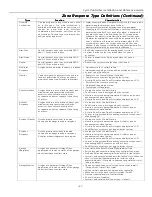
This feature allows the Central Station operator to listen, talk to or conduct a two-way conversation with an 
individual(s) at the premises. It also assists the operator in gathering information about the nature and location 
of the alarm that may be helpful in responding to police and fire departments. All Lyric Controllers are capable 
of supporting the Two-Way Voice feature. The Lyric Controller does not make system announcements when the 
Two-Way Voice feature is active.  

If a Wi-Fi connection is being used for Two-Way Voice (AAV), sufficient bandwidth must be available. 


  AAV requires a continuous Wi-Fi upload/download bandwidth of 90kbps for proper operation.  


  Wi-Fi bandwidth less than 90kbps may result in degraded performance. 

Activation

Activation

Activation

Activation    


Fire and CO alarms will 

Fire and CO alarms will 

Fire and CO alarms will 

Fire and CO alarms will prevent the 

prevent the 

prevent the 

prevent the Lyric 

Lyric 

Lyric 

Lyric Controller

Controller

Controller

Controller    from starting 

from starting 

from starting 

from starting an AAV session.  A new Fire or 

an AAV session.  A new Fire or 

an AAV session.  A new Fire or 

an AAV session.  A new Fire or 

CO alarm will end an AAV session that is 

CO alarm will end an AAV session that is 

CO alarm will end an AAV session that is 

CO alarm will end an AAV session that is in progress. 

in progress. 

in progress. 

in progress.     

The controller sends the “alarm message” followed by a “Listen-in-to-Follow message” (Contact ID® code 606) 
to the Central Station. The Listen-in-to-Follow message causes the Central Station’s digital receiver to 
temporarily hold the phone line for approximately 1 minute.  When the controller receives the “kissoff” from the 
Central Station, indicating that the alarm message has been received, the Two-Way Voice (AAV) feature is 
activated in the (default) “Listen Mode” and sirens and keypad sounds are discontinued. The controller transmits 
a beep acknowledgment to the Central Station, once per second. The beep alternates between two tones and 
indicates that the controller is waiting for a session command from the Central Station operator.  Once a 
command is issued the beep acknowledgement is discontinued, however, if a command is not issued within two 
minutes the system will “time out” and the call will be terminated. 

Operator Commands

Operator Commands

Operator Commands

Operator Commands  
The Central Station operator begins the session, which last 5 minutes, by entering one of the valid AAV 
commands shown in the table below. The session may be extended 5 minutes, without changing the operating 
mode, by pressing the [7] key on the touch-tone phone.  Selecting another operating mode also resets the 
session an additional 5 minutes.  During the last minute of the 5 minute, session, the controller generates two 
beeps every 30 seconds to alert the Central Station operator that the session is about to time out. The Central 
Station operator may then extend the session by pressing the [7] key on the touch-tone phone.  If the session is 
not extended, the phone line is disconnected and the session is ended. Sessions may be ended at any time by 
pressing the [9] key on the touch-tone phone.  The AAV modes are described as follows:   

Note: 

Note: 

Note: 

Note:  When  entering  AAV  commands  make  sure  the  Central  Station  receiver  has  been  disconnected 

from the phone line, otherwise AAV commands may not go through. 

  Key

Key

Key

Key


Function

Function

Function

Function 

1


Talk Mode:  Pressing the [1] key on the touch tone phone, enables one-way voice communication 
from the Central Sation to the violated premises, and allows the operator to communicate through 
the controller’s built-in speaker. In this mode the controller’s Panic button is lit Red and the Home 
button is alternately lit Red and Green. 

2


VOX (Voice) Mode:  Pressing the [2] key on the touch-tone phone, enables two-way voice 
communications between the Central Station and the violated premises via the controller’s built-in 
speaker and microphone. In this mode the controller’s Panic button is lit Red and the Home button is 
alternately lit Red and Green. 

3


Listen Mode: Pressing the [3] key on the touch-tone phone, Enables one-way audio from the violated 
premises to the Central Station.  The Listen Mode is the start up default mode of the voice feature and 
allows the operator to listen through the controller microphone. This mode does not affect the existing 
LED pattern. 

7


Extends the session 5 minutes without changing its operating mode. 

9


Ends the session and disconnects the phone line. 

Содержание Lyric LCP500-L

Страница 1: ...Lyric Lyric Lyric Lyric Controller Installation and Reference Guide Ref LCP500 L LCP500 LC 800 18076 11 15 Rev C ...

Страница 2: ...connections to an AC source or phone lines are made If detectors are not so located a fire within the room could prevent the control from reporting a fire or an intrusion THIS CONTROL COMPLIES WITH NFPA REQUIREMENTS FOR TEMPORAL PULSE THIS CONTROL COMPLIES WITH NFPA REQUIREMENTS FOR TEMPORAL PULSE THIS CONTROL COMPLIES WITH NFPA REQUIREMENTS FOR TEMPORAL PULSE THIS CONTROL COMPLIES WITH NFPA REQUI...

Страница 3: ...Types 13 Transmitter Battery Life 13 RF Transmitter Loop Numbers 14 Mechanics Mechanics Mechanics Mechanics of of of of Programming Programming Programming Programming 15 Navigating Menus 15 Touch screen Display 15 Keypad Lockout 15 Navigation Keys 16 Home Screen 16 Security Screen 17 Master User Tools Screen 17 Programming 18 Enter Installer Programming Mode 18 Loading Factory Defaults 19 Select ...

Страница 4: ...cifications Specifications 36 Contacting Technical Support Contacting Technical Support Contacting Technical Support Contacting Technical Support 36 Glossary Glossary Glossary Glossary 37 Index Index Index Index 38 Summary Summary Summary Summary of of of of Connect Connect Connect Connections Diagram ions Diagram ions Diagram ions Diagram 39 Warranty Information Warranty Information Warranty Info...

Страница 5: ...er for user recorded messages Voice Announcement of System and Zone Status Ten User selectable Chime Sounds Automatic Stay Arming Night Stay Arming 48 User Codes Installer Master Guest Duress Panic Functions Police Fire Medical Programmable Reminders Video Camera Control requires Wi Fi connection Supports Mobile Devices Tablet iPAD etc that duplicate functions of the Lyric Controller i e Security ...

Страница 6: ...s Temporal 4 Pulse Output for carbon monoxide alarms Audio Alarm Verification AAV Programming Programming Programming Programming Options stored in EEROM Can be uploaded downloaded or controlled via AlarmNet 360 using capable Cellular or Wi Fi Communications Module Flash Downloading Other Features Other Features Other Features Other Features Exit Error feature detects difference between an actual ...

Страница 7: ...nto controller s rear case 2 Install the battery retainer 3 Secure the battery retainer with the provided screw 4 Connect the battery pack connector to the receptacle on the back of the controller 5 Align the slots on the back of the controller with the hooks on the wall mount as shown below 6 Once attached insert the screw to secure the controller to the wall mount 7 Plug the power supply into a ...

Страница 8: ...ow 6 Once attached insert the screw to secure the Lyric to the wall mount NOTE NOTE NOTE NOTE If a Cellular Communication Module is being installed verify the module s signal strength before selecting a final mounting location Refer to Checking the Signal Strength in the Communications Module section Wall Mounting Wall Mounting Wall Mounting Wall Mounting NOTE NOTE NOTE NOTE When selecting a locat...

Страница 9: ...ack Plate Replace the Back Plate 1 Remove the screw securing the rear cover to the controller 2 Remove the rear cover NOTE NOTE NOTE NOTE If using the high capacity 24 hour backup battery Kit LCP500 24B battery p n 300 03866 AIO remove the battery retainer clip The clip is not required when the desk mount is installed 3 Feed the field wiring through the appropriate openings in the rear cover inclu...

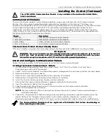
Страница 10: ...ter power supply into the AC outlet until after all wiring connections have been made all wiring connections have been made all wiring connections have been made all wiring connections have been made Wiring Overview Wiring Overview Wiring Overview Wiring Overview The following summarizes the electrical connections associated with the Lyric Controller Follow the steps and refer to the figure below ...

Страница 11: ...s and not co in 20 cm from all persons and not co located or operated in conjunction with any other located or operated in conjunction with any other located or operated in conjunction with any other located or operated in conjunction with any other transmitter except in accordance with FCC multi transmitter except in accordance with FCC multi transmitter except in accordance with FCC multi transm...

Страница 12: ...ng large metal components provides adequate signal strength for proper operation To check signal strength perform the following test Check Signal Strength Check Signal Strength Check Signal Strength Check Signal Strength 1 With the System in the Installer Programming mode select the Comm Diagnostics button and then select the Cellular Information button The Cellular Information will be displayed a...

Страница 13: ...s wireless transmitters wireless transmitters wireless transmitters have not been have not been have not been have not been evaluated by evaluated by evaluated by evaluated by ETL ETL ETL ETL House Identification House Identification House Identification House Identification If a RF House ID RF House Code is required to establish proper communication the same two digit code 01 31 must be programme...

Страница 14: ...TY LOOP 2 HIGH SENSITIVITY LOOP 3 TEMP LOOP 4 TAMPER SERIAL 1 LOOP 1 HEAT SMOKE LOOP 2 MAINTENANCE LOOP 3 LOW TEMP SERIAL 2 LOOP 1 CO LOOP 2 END OF LIFE LOOP 1 LOOP 1 LOOP 1 LOOP 1 LOOP 1 5806 5806W3 5807 5808 5808LST 5808W3 ENROLL AS SUPERVISED LOOP 1 LOOP 1 5809 ENROLL AS SUPERVISED LOOP 1 5814 ENROLL AS SUPERVISED 5804E ENROLL AS BUTTON 5815WG 5815WG BR ENROLL AS SUPERVISED 5811 ENROLL AS SUPER...

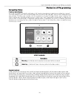
Страница 15: ...not When the system is armed the Home Function key is lit Red lyric 009 V2 Ready To Arm Chime Notices Automation Settings Video Smart Scenes 66F Mostly Sunny 5 Day Forecast December 31 2014 Security 12 00PM LYRIC LYRIC LYRIC LYRIC Controller Controller Controller Controller Key Key Key Key Description Description Description Description Panic key Panic key Panic key Panic key Initiates panic alarm...

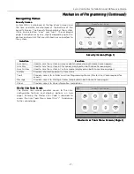
Страница 16: ...is displayed at the top of screen In addition to the system status the Home Screen displays the current date and time and Security Automation Video Smart Scenes Notices Settings and Help Videos icons on two pages When Total Connect Services are connected and web content is enabled the current weather forecast and a 5 Day Forecast button are displayed Selectable options are displayed on two pages S...

Страница 17: ...Function Function Function Arm Away Used to Arm the system in Away mode displayed on both Home Screen pages Arm Stay Used to Arm the system in Stay mode displayed on both Home Screen pages Arm Custom Used to Arm the system in Custom mode displayed on both Home Screen pages System Provides information about system status Tools Provides access to Installer and User Programming Menus Master User Code...

Страница 18: ...stem Standby Screen System Standby Screen System Standby Screen System Programming lyric 026 V0 System Type Installer Code Communicator Date Time Comm Diagnostics Zones Reporter Keys System Settings Sounder Installer Tools Menu Installer Tools Menu Installer Tools Menu Installer Tools Menu Screen Screen Screen Screen 1 Power up the controller and allow it to boot up System Standby is displayed on ...

Страница 19: ...ion selected Select a Default Configuration Select a Default Configuration Select a Default Configuration Select a Default Configuration SCREEN SCREEN SCREEN SCREEN ACTION ACTION ACTION ACTION System Programming lyric 039 V1 Z Wave Default Config Reset Master Code Language RF Keypad 1 Select Default Config Note Note Note Note For a list of the pre programmed defaults refer to the Programming Defau...

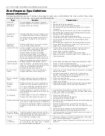
Страница 20: ... area where immediate notification of an entry is desired Instant alarm when armed in Away Stay Night Stay Stay Instant or Away Instant night mode Provides a latched trouble sounding from the keypad and if desired a Central Station report when disarmed day 24 hour Silent Alarm Usually assigned to a zone containing an Emergency button silent emergency Sends a report to the Central Station but provi...

Страница 21: ...s or contacts on doors and windows or asset protection within the premises Used to track activity of the occupant and alert occupant of the activity of others No reports to the Central Station Fault restore events are logged by the system Monitors entry into a monitored area Activates a one time announcement when faulted Activity Zone No and Zone Descriptor displayed on LCD General Response Assign...

Страница 22: ...mergency Important Important Important Important For the silent panic functions to be of practical value the system must be connected to a Central Station Security Codes Security Codes Security Codes Security Codes Installer Code Installer Code Installer Code Installer Code The installer programs the 4 digit Installer Code initially as part of the programming procedure The factory default Installe...

Страница 23: ... the system only if it was used to arm it In addition the Installer Code cannot disarm the system if it was armed by pressing and holding a Quick Arm button The Guest Code can disarm the system only if it was used to arm it In addition the Guest Code cannot disarm the system if it was armed by pressing and holding a Quick Arm button Duress code sends a special code to the Central Station when used...

Страница 24: ...r Ready To Arm 988 RF Jam 5800 Series Wireless Device Automation Icon Z Wave Node Failure OR Z Wave Controller Not Ready Armed Away 990 RF Jam SiX Series Wireless Device Garage Door Open Armed Stay 998 Local Alarm Wi Fi source present and signal strength Armed Night Stay Door Open No Wi Fi source Armed Custom Window Open Restart Timer Fire OR Heat Sensor Battery Low Environmental Bypassed Zones Fl...

Страница 25: ...ounds are discontinued The controller transmits a beep acknowledgment to the Central Station once per second The beep alternates between two tones and indicates that the controller is waiting for a session command from the Central Station operator Once a command is issued the beep acknowledgement is discontinued however if a command is not issued within two minutes the system will time out and the...

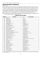
Страница 26: ...Interior 134 Alarm Entry Exit Entry Exit 135 Alarm Day Night Day Night 137 Alarm Tamper Tamper 145 Expansion Module Tamper Exp Module Tamper 146 Silent Burglary Silent Burglary 150 24 Hour Non Burglary 24 Hr Non Burglary 162 Carbon Monoxide Detected CO Detected 301 Trouble AC Loss AC Loss 302 Trouble Low System Battery System Low Battery 305 Trouble System Reset System Reset 308 System shutdown Sy...

Страница 27: ...o Thermostat Mode auto 3404 Thermostat Mode Aux Em Heat Thermostat Mode aux em Heat 3405 Thermostat Fan Mode Auto Thermostat Fan Mode auto 3406 Thermostat Fan Mode Manual On Thermostat Fan Mode manual on 3407 Thermostat Fan Mode Circulate Thermostat Fan Mode circulate 3408 Thermostat Set Heat Point Thermostat Set heat point 3409 Thermostat Set Cool Point Thermostat Set cool point 3410 Thermostat H...

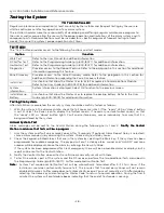
Страница 28: ...ty system should be carefully tested as follows 1 With the system in the disarmed state check that all zones are intact If the ready LED or Home button is not lit select the Zones icon to display the faulted zone s If necessary restore faulted zone s so that the ready LED or Home button lights Fault and restore every sensor individually to assure that it is being monitored by the system Armed Syst...

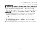
Страница 29: ...ill be displayed Enter Zone Discovery Enter Zone Discovery Enter Zone Discovery Enter Zone Discovery 1 With the System in the Installer Programming mode select the Test button and then select the Zone Discovery button The Zone Discovery button will be highlighted indicating that the mode is active Exit Zone Discovery Exit Zone Discovery Exit Zone Discovery Exit Zone Discovery 1 Select the Home key...

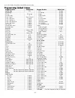
Страница 30: ...Week First System Settings Communicator Entry Delay 1 30 Seconds Communications Path WiFi Entry Delay 2 30 Seconds APL Enabled Exit Delay 60 Seconds City ID Blank Backlight Timeout No CS ID Blank Quick Arm Yes Sub ID Blank Quick Exit Yes Supervision 30 Days Restart Exit Time Yes Old Alarm Time 10 Minutes Force Bypass No Remote Acc Comm Disabled Exit Warning Yes Multi Mode Comm Disabled Auto Stay A...

Страница 31: ...a n a 135 3 Key Fob Arm Away Yes Disabled Button n a n a 136 2 Key Fob Disarm Yes Disabled Button n a n a 137 4 Key Fob Arm Stay Yes Disabled Button n a n a 138 1 Key Fob No Response No Disabled Button n a n a 280 Temperature Monitor Yes Disabled High Temp n a n a 281 Temperature Monitor Yes Disabled Low Temp n a n a 282 Temperature Monitor Yes Disabled High Temp n a n a 283 Temperature Monitor Ye...

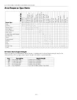
Страница 32: ...x x x x x x x Glass Break x x x x x Smoke Detector x x Heat Sensor x Carbon Monoxide Detector x Temperature x x Flood x x Environmental x x Medical x x x Fire x x Police x x x x Garage Door x x Other x x x x x x x x x x x x x x x x x x x x x x x x x x x SiX SiX SiX SiX Series Device Series Device Series Device Series Device Signal Signal Signal Signal Strength Strength Strength Strength Signal str...

Страница 33: ...Industrie Canada Son fonctionnement est soumis aux conditions suivantes 1 Cet appareil ne doit pas causer d interferences nuisibles 2 Cet appareil doit accepter toute interference reçue y compris les interferences causant une reception indésirable RF Exposure Warning RF Exposure Warning RF Exposure Warning RF Exposure Warning The antenna s used for this transmitter must be installed to provide a s...

Страница 34: ...otection and intrusion can only be detected in unobstructed areas covered by those beams They cannot detect motion or intrusion that takes place behind walls ceilings floors closed doors glass partitions glass doors or windows Mechanical tampering masking painting or spraying of any material on the mirrors windows or any part of the optical system can reduce their detection ability Passive Infrare...

Страница 35: ...ing Guide Installation and Setup Guide or Programming Guide Installation and Setup Guide or Programming Guide Installation and Setup Guide or Programming Guide Reporter Reporter Reporter Reporter Report Selection Exit Error Not selectable Enabled Enabled Recent Closing Not selectable Enabled Enabled Alarm Cancel Enabled or Disabled Enabled Enabled Reporter Reporter Reporter Reporter Options Number...

Страница 36: ...dwire Zone Hardwire Zone Hardwire Zones s s s 2K ohms End of Line Resistor EOLR Normally Open N O and Normally Closed N C For patent information see www honeywell com patents Contacting Technical Support Contacting Technical Support Contacting Technical Support Contacting Technical Support PLEASE before you call Technical Support PLEASE before you call Technical Support PLEASE before you call Tech...

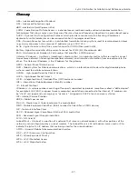
Страница 37: ...et Radio Service GSM Global System for Mobile communications which is an international standard for digital mobile phone systems used for cellular communication HSDPA High Speed Downlink Packet Access HSPA High Speed Packet Access ICCID Integrated Circuit Card Identifier SIM Card serial number IMEI International Mobile Equipment Identity number IP Internet Protocol IP Address A unique number consi...

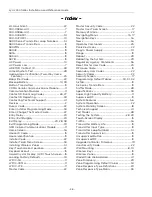
Страница 38: ...Liquid Crystal Display LCD Touch Screen 15 Loading Factory Defaults 19 LYRIC 3G 11 LYRIC CDMA 11 LYRIC LTE 11 Master Code 22 Master Security Code 22 Master User Tools Screen 17 Memory of Alarm 22 Navigating Menus 15 17 Navigation Keys 16 News 16 Operator Commands 25 Panic Key Icons 22 Plug In Power Supply 10 Range 13 Reboot 29 Rebooting the System 29 Regulatory Agency Statements 36 Reset Master Us...

Страница 39: ...ING DEVICES SHALL BE CONNECTED TO THESE CIRCUITS UNLESS APPROVED BY THE LOCAL AUTHORITY HAVING JURISDICTION WARNING 5806W3 10 seconds 30 seconds 03 126 ZONE TYPE SUPERVISED FIRE WITH VERIFICATION USB PORT BATTERY RECEPTACLE TAMPER TERMINAL BOARD 2K OHM EOLR 2K OHM EOLR HARD WIRED ZONE POWER SUPPLY 300 04705V1 300 04063V1 CANADA HARD WIRED ZONE HWZ2 GND HWZ1 9VDC GND IMPORTANT NOTES ABOUT EXTERNAL ...

Страница 40: ...or the latest warranty information please go to www honeywell com security hsc resources wa For patent information see www honeywell com patents MyWebTech Warranty Patents 2 Corporate Center Drive Suite 100 P O Box 9040 Melville NY 11747 Copyright 2015 Honeywell International Inc www honeywell com security Ê800 18076XŠ 800 18076 11 15 Rev C ...

Отзывы: